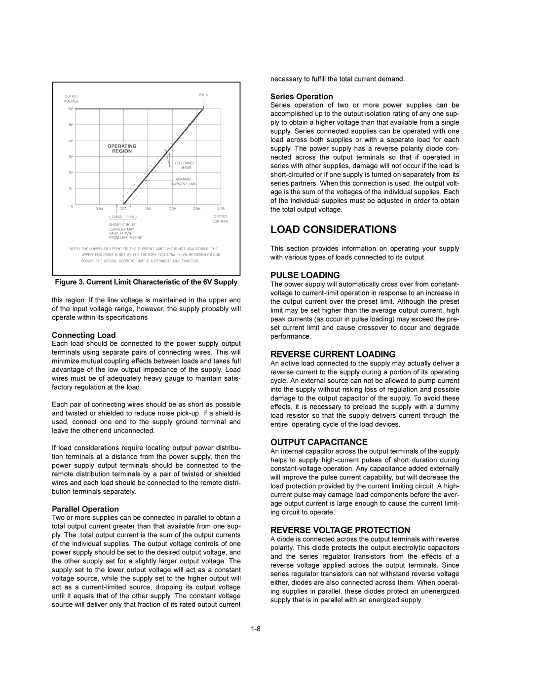
Figure 3. Current Limit Characteristic of the 6V Supply
this region. If the line voltage is maintained in the upper end of the input voltage range, however, the supply probably will operate within its specifications
Connecting Load
Each load should be connected to the power supply output terminals using separate pairs of connecting wires. This will minimize mutual coupling effects between loads and takes full advantage of the low output impedance of the supply. Load wires must be of adequately heavy gauge to maintain satis- factory regulation at the load.
Each pair of connecting wires should be as short as possible and twisted or shielded to reduce noise
If load considerations require locating output power distribu- tion terminals at a distance from the power supply, then the power supply output terminals should be connected to the remote distribution terminals by a pair of twisted or shielded wires and each load should be connected to the remote distri- bution terminals separately.
Parallel Operation
Two or more supplies can be connected in parallel to obtain a total output current greater than that available from one sup- ply. The total output current is the sum of the output currents of the individual supplies. The output voltage controls of one power supply should be set to the desired output voltage, and the other supply set for a slightly larger output voltage. The supply set to the lower output voltage will act as a constant voltage source, while the supply set to the higher output will act as a
necessary to fulfill the total current demand.
Series Operation
Series operation of two or more power supplies can be accomplished up to the output isolation rating of any one sup- ply to obtain a higher voltage than that available from a single supply. Series connected supplies can be operated with one load across both supplies or with a separate load for each supply. The power supply has a reverse polarity diode con- nected across the output terminals so that if operated in series with other supplies, damage will not occur if the load is
LOAD CONSIDERATIONS
This section provides information on operating your supply with various types of loads connected to its output.
PULSE LOADING
The power supply will automatically cross over from constant- voltage to
REVERSE CURRENT LOADING
An active load connected to the supply may actually deliver a reverse current to the supply during a portion of its operating cycle. An external source can not be allowed to pump current into the supply without risking loss of regulation and possible damage to the output capacitor of the supply. To avoid these effects, it is necessary to preload the supply with a dummy load resistor so that the supply delivers current through the entire operating cycle of the load devices.
OUTPUT CAPACITANCE
An internal capacitor across the output terminals of the supply helps to supply
REVERSE VOLTAGE PROTECTION
A diode is connected across the output terminals with reverse polarity. This diode protects the output electrolytic capacitors and the series regulator transistors from the effects of a reverse voltage applied across the output terminals. Since series regulator transistors can not withstand reverse voltage either, diodes are also connected across them. When operat- ing supplies in parallel, these diodes protect an unenergized supply that is in parallel with an energized supply.