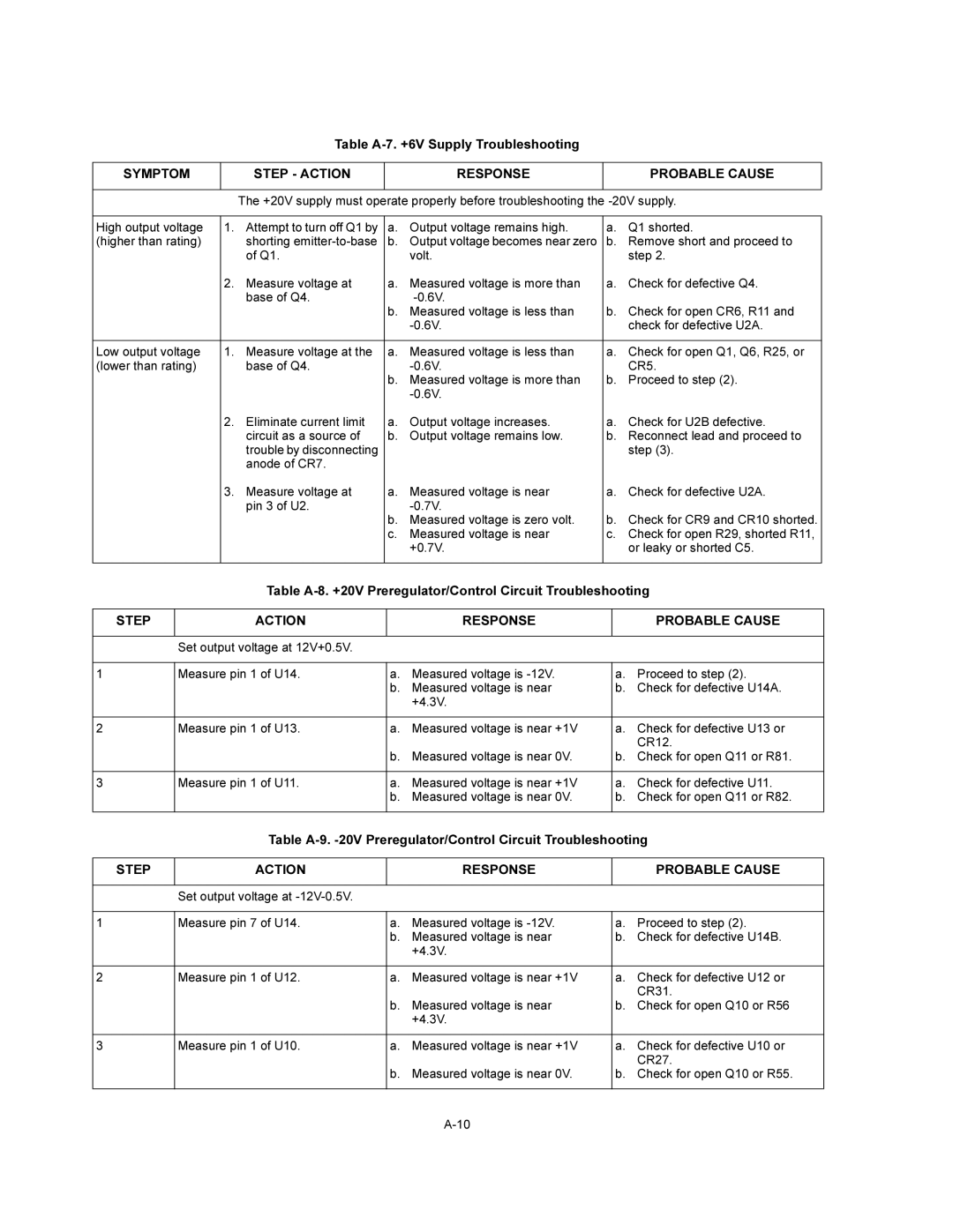
Table
SYMPTOM |
| STEP - ACTION |
| RESPONSE |
| PROBABLE CAUSE |
|
|
|
|
| ||
|
| The +20V supply must operate properly before troubleshooting the | ||||
|
|
|
|
|
|
|
High output voltage | 1. | Attempt to turn off Q1 by | a. | Output voltage remains high. | a. | Q1 shorted. |
(higher than rating) |
| shorting | b. | Output voltage becomes near zero | b. | Remove short and proceed to |
|
| of Q1. |
| volt. |
| step 2. |
| 2. | Measure voltage at | a. | Measured voltage is more than | a. | Check for defective Q4. |
|
| base of Q4. |
|
|
| |
|
|
| b. | Measured voltage is less than | b. | Check for open CR6, R11 and |
|
|
|
|
| check for defective U2A. | |
|
|
|
|
|
|
|
Low output voltage | 1. | Measure voltage at the | a. | Measured voltage is less than | a. | Check for open Q1, Q6, R25, or |
(lower than rating) |
| base of Q4. |
|
| CR5. | |
|
|
| b. | Measured voltage is more than | b. | Proceed to step (2). |
|
|
|
|
|
| |
| 2. | Eliminate current limit | a. | Output voltage increases. | a. | Check for U2B defective. |
|
| circuit as a source of | b. | Output voltage remains low. | b. | Reconnect lead and proceed to |
|
| trouble by disconnecting |
|
|
| step (3). |
|
| anode of CR7. |
|
|
|
|
| 3. | Measure voltage at | a. | Measured voltage is near | a. | Check for defective U2A. |
|
| pin 3 of U2. |
|
|
| |
|
|
| b. | Measured voltage is zero volt. | b. | Check for CR9 and CR10 shorted. |
|
|
| c. | Measured voltage is near | c. | Check for open R29, shorted R11, |
|
|
|
| +0.7V. |
| or leaky or shorted C5. |
|
|
|
|
|
|
|
Table
STEP | ACTION |
| RESPONSE |
| PROBABLE CAUSE |
|
|
|
|
|
|
| Set output voltage at 12V+0.5V. |
|
|
|
|
|
|
|
|
| |
1 | Measure pin 1 of U14. | a. | Measured voltage is | a. Proceed to step (2). | |
|
| b. Measured voltage is near | b. | Check for defective U14A. | |
|
|
| +4.3V. |
|
|
|
|
|
|
| |
2 | Measure pin 1 of U13. | a. | Measured voltage is near +1V | a. Check for defective U13 or | |
|
|
|
|
| CR12. |
|
| b. Measured voltage is near 0V. | b. Check for open Q11 or R81. | ||
|
|
|
|
| |
3 | Measure pin 1 of U11. | a. | Measured voltage is near +1V | a. Check for defective U11. | |
|
| b. | Measured voltage is near 0V. | b. | Check for open Q11 or R82. |
|
|
|
|
|
|
Table
STEP | ACTION |
| RESPONSE |
| PROBABLE CAUSE |
|
|
|
|
|
|
| Set output voltage at |
|
|
|
|
|
|
|
|
| |
1 | Measure pin 7 of U14. | a. | Measured voltage is | a. Proceed to step (2). | |
|
| b. Measured voltage is near | b. | Check for defective U14B. | |
|
|
| +4.3V. |
|
|
|
|
|
|
| |
2 | Measure pin 1 of U12. | a. | Measured voltage is near +1V | a. Check for defective U12 or | |
|
|
|
|
| CR31. |
|
| b. Measured voltage is near | b. | Check for open Q10 or R56 | |
|
|
| +4.3V. |
|
|
|
|
|
|
| |
3 | Measure pin 1 of U10. | a. | Measured voltage is near +1V | a. Check for defective U10 or | |
|
|
|
|
| CR27. |
|
| b. | Measured voltage is near 0V. | b. | Check for open Q10 or R55. |
|
|
|
|
|
|