The
To measure the ripple and noise of the
a.Connect the test equipment across the output of the +20V supply as shown in Figure
b.Turn on the supply and push +20V METER switch.
c.Turn up output voltage to the full rated value.
d.Set the oscilloscope to AC mode and bandwidth to 20 MHz.
e.Check that the
f.Repeat for the remaining supply outputs.
Common Mode Current (CMI)
Definition : Common mode current is that ac current compo- nent which exists between any or all supply or output lines and chassis ground.
To measure the common mode current:
a.Connect the full load for +6V output.
b.Connect a 100 kW resistor(RS) and a 2200 pF capacitor in parallel between common terminal(COM) and chassis ground.
c.Connect the DVM across RS.
d.Turn on the supply.
e.Record the voltage across RS and convert it to current by dividing this voltage by RS.
f.Check that the current is less than 1 mA.
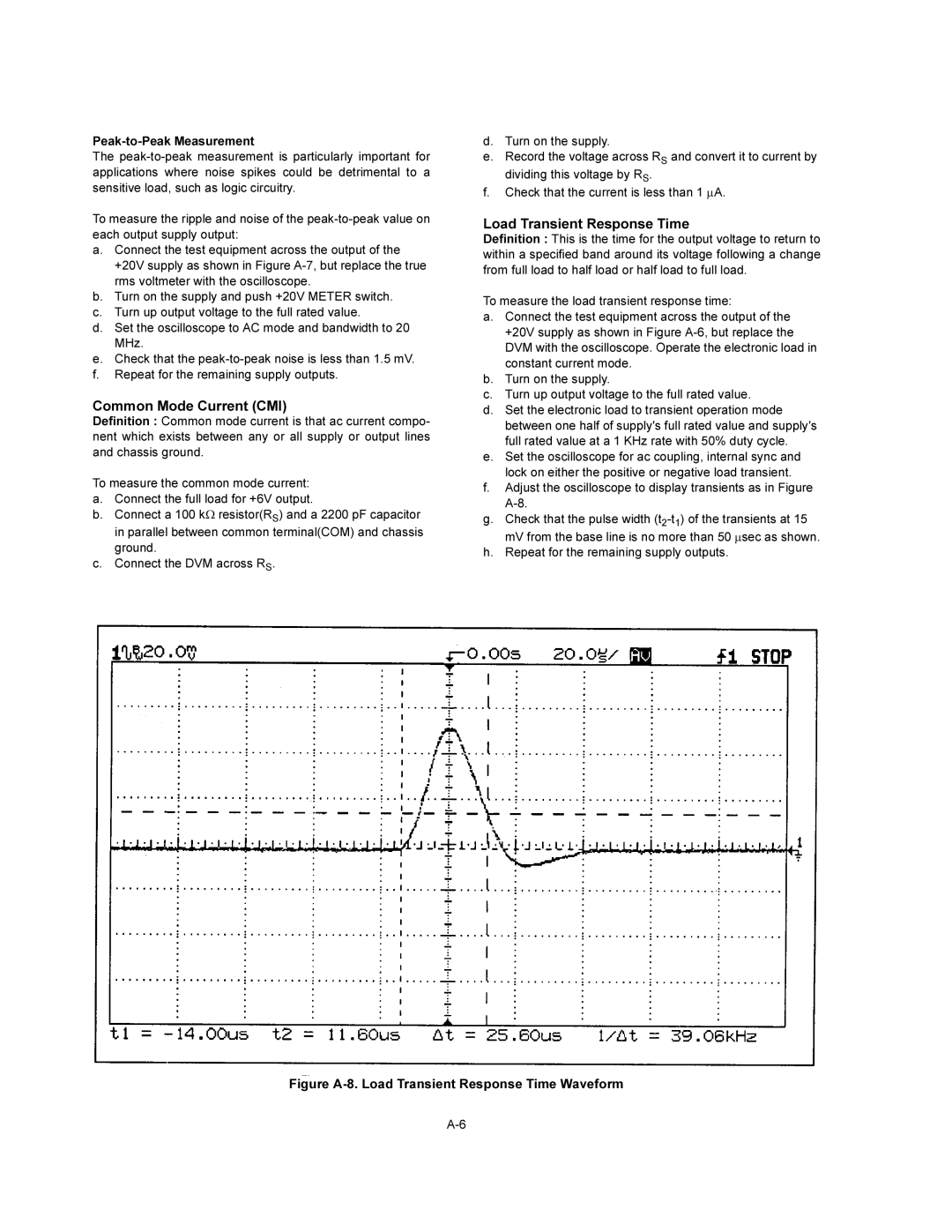
Load Transient Response Time
Definition : This is the time for the output voltage to return to within a specified band around its voltage following a change from full load to half load or half load to full load.
To measure the load transient response time:
a.Connect the test equipment across the output of the
+20V supply as shown in Figure
b.Turn on the supply.
c.Turn up output voltage to the full rated value.
d.Set the electronic load to transient operation mode between one half of supply's full rated value and supply's full rated value at a 1 KHz rate with 50% duty cycle.
e.Set the oscilloscope for ac coupling, internal sync and lock on either the positive or negative load transient.
f.Adjust the oscilloscope to display transients as in Figure
g.Check that the pulse width
h.Repeat for the remaining supply outputs.