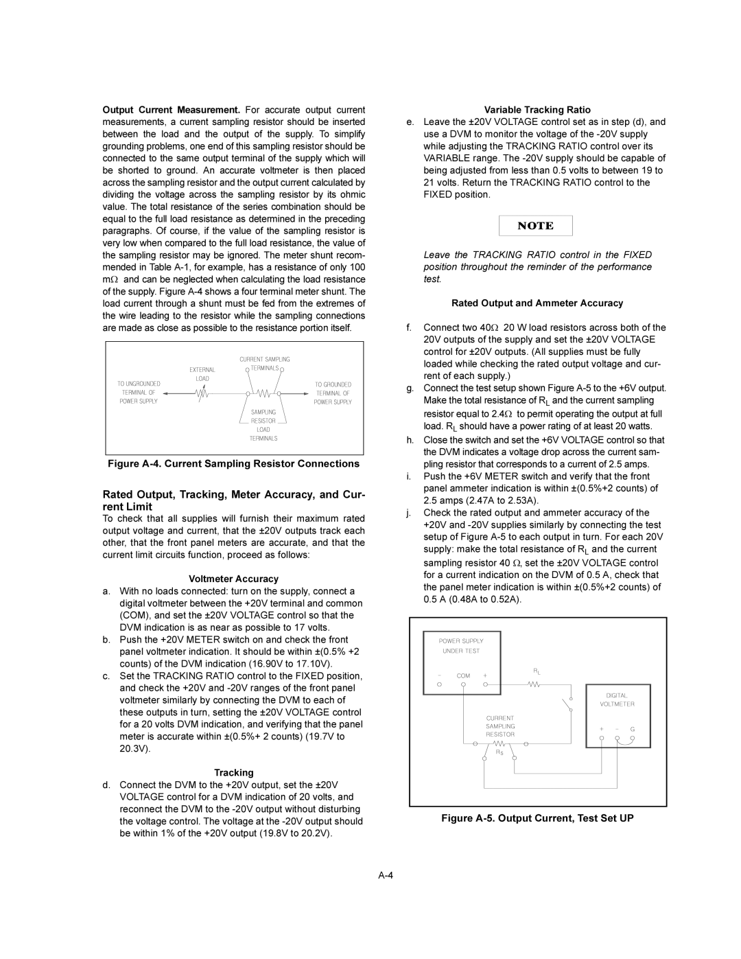
Output Current Measurement. For accurate output current measurements, a current sampling resistor should be inserted between the load and the output of the supply. To simplify grounding problems, one end of this sampling resistor should be connected to the same output terminal of the supply which will be shorted to ground. An accurate voltmeter is then placed across the sampling resistor and the output current calculated by dividing the voltage across the sampling resistor by its ohmic value. The total resistance of the series combination should be equal to the full load resistance as determined in the preceding paragraphs. Of course, if the value of the sampling resistor is very low when compared to the full load resistance, the value of the sampling resistor may be ignored. The meter shunt recom- mended in Table
Figure A-4. Current Sampling Resistor Connections
Rated Output, Tracking, Meter Accuracy, and Cur- rent Limit
To check that all supplies will furnish their maximum rated output voltage and current, that the ±20V outputs track each other, that the front panel meters are accurate, and that the current limit circuits function, proceed as follows:
Voltmeter Accuracy
a.With no loads connected: turn on the supply, connect a digital voltmeter between the +20V terminal and common (COM), and set the ±20V VOLTAGE control so that the DVM indication is as near as possible to 17 volts.
b.Push the +20V METER switch on and check the front panel voltmeter indication. It should be within ±(0.5% +2 counts) of the DVM indication (16.90V to 17.10V).
c.Set the TRACKING RATIO control to the FIXED position, and check the +20V and
Tracking
d.Connect the DVM to the +20V output, set the ±20V VOLTAGE control for a DVM indication of 20 volts, and reconnect the DVM to the
Variable Tracking Ratio
e.Leave the ±20V VOLTAGE control set as in step (d), and use a DVM to monitor the voltage of the
Leave the TRACKING RATIO control in the FIXED position throughout the reminder of the performance test.
Rated Output and Ammeter Accuracy
f.Connect two 40W 20 W load resistors across both of the 20V outputs of the supply and set the ±20V VOLTAGE control for ±20V outputs. (All supplies must be fully loaded while checking the rated output voltage and cur- rent of each supply.)
g.Connect the test setup shown Figure
h.Close the switch and set the +6V VOLTAGE control so that the DVM indicates a voltage drop across the current sam- pling resistor that corresponds to a current of 2.5 amps.
i.Push the +6V METER switch and verify that the front panel ammeter indication is within ±(0.5%+2 counts) of
2.5amps (2.47A to 2.53A).
j.Check the rated output and ammeter accuracy of the +20V and
0.5A (0.48A to 0.52A).