User’s Guide
Legal Notices
Agilent Technologies, Inc
Frame or chassis terminal
Safety Notices
On supply Off supply
This Book
Contents
Output Programming Example Trigger Programming Example
Supplemental Characteristics
Verification
Quick Reference
Output Features
Agilent N5700 DC Power Supplies At a Glance
System Features
Model Ratings
Programmable Functions
Model Voltage Current Range
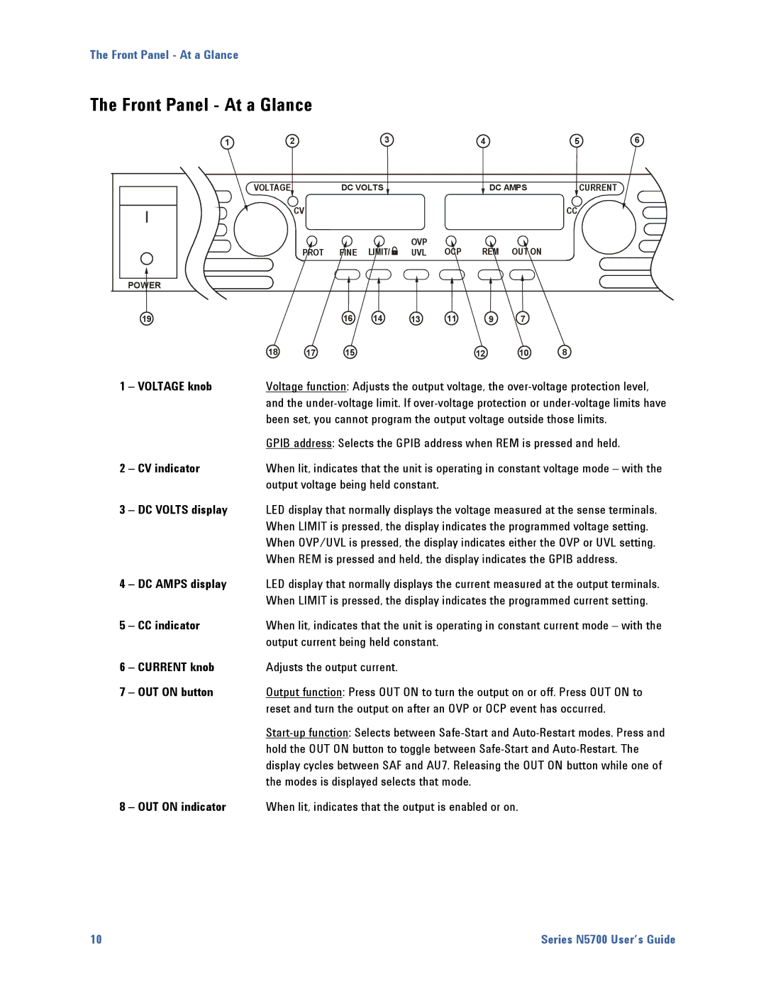
Front Panel At a Glance
Voltage knob
Limit indicator
REM indicator
OCP indicator
Fine indicator
Rear Panel At a Glance
Enable/Disable control
J2 Sense Connector
SW1 Setup Switch
Remote sense + Local sense + Not used
J1 Analog Programming Connector
Complete description of all programming commands
Scpi Programming Commands At a Glance
Subsystem Commands
Scpi Command Description
Common Commands
Command Description
Installation
Models
Accessories
General Information
Options
Inspecting the Unit
Installing the Unit
Safety Considerations
Environment
Than 6 mm into the sides of the unit
Rack Installation
Cleaning
Unit
Input Connections for 750W units
Connecting the Line Cord
Power cord, resulting in fire
Input Connections for 1500W units
Screw-on Locknut
M3x8 Flat Head Screws Places Cover Assembled Strain Relief
Shorted, whichever is greater
Wire Size
Tightened
For 5 a For 10 a For 20A For 50A For 150A
How to mount the bus-bar shield to the chassis
Output voltage of the power supply
Securely attached. Do not use unterminated wires for load
Load Connections for 6V to 60V Models
10 mm 0.39
Wire Size
Load Connections for 80V to 600V Models
Torque
Output Voltage Sensing
Output Voltage Sensing
Remote Sensing
Local Sensing
Plug Type
Load Considerations
Multiple Loads
Output Noise and Impedance Effects
Inductive Loads
Connected in parallel
Parallel Connections
Grounding the Output
Local Sensing
Setting up the Slave Units
Setting up the Master Unit
Remote Sensing
Series Connections
Setting the Over-Voltage Protection
Setting the Over-Current Protection
Connected in series
Local Sensing Remote Sensing
Separated and floated from each other
Mating Plug
J1 Connector Connections
Voltage of the power supply
Extraction tool
Operating the Power Supply Locally
Before Check-Out
On check-out procedure
Turn-On Check-Out
Constant Voltage Check
Constant Current Check
UVL Check
OCP Check
Constant Current Mode
Constant Voltage Mode
Normal Operation
Over-Voltage Protection
CV/CC Mode Crossover
CV/CC Signal
Limit the sink current to less than 10mA
Under-Voltage Limit
Over-Current Protection
Front Panel Lock-Out
Over-Temperature Protection
Power-Fail Protection
SYSTCOMMRLST, it cannot be unlocked from the front panel
OUT on button
SW1 switch SO Signal Level Output Display
Output On/Off Control
Output Shut-Off Terminals
SW1 switch ENA+/ENA- pins Output Display Prot Indicator
Enable/Disable Terminals
Power Supply OK Signal
Safe-Start and Auto-Restart
Daisy-Chained Output Shut-down
Analog Programming of Output Voltage and Current
Sense terminal, as it may damage the unit
Analog Programming Control Terminals
Voltage Programming of Output Voltage and Current
Resistance Programming of Output Voltage and Current
SW1 switch Voltage Programming
Down default
Current Programming
J1 pin 12 is the signal common for J1 pins 11
Down default J1 pin Voltage Monitor Current Monitor
External Monitoring of Output Voltage and Current
Page
ROM included with this manual
Communication using a choice of three interfaces GPIB, USB,
Configuring the Interface
Agilent N5700 power supplies support remote interface
LAN. All three interfaces are live at power-on
USB023912055serialnumber0INSTR
USB Interface
USB ID string is
Parameters as well as change its Alias name
Application
LAN Interface
Microsystem’s website
Setup Utility as described later in this section
Modify Configuration tab. All LAN parameters can be
Reconfigured using this
N5700 unit. It will also indicate the IP address assigned
Configuring the LAN parameters
Configuring the Interface
Configuring the Interface
Using the Setup Utility
Tips for the using the LAN interface
Using Visa
Multiple Commands in a Message
Scpi Commands an Introduction
Syntax
Which would result in a syntax error
Commands from Different Subsystems
Message Unit
Command Terminators
Queries
Discrete and String Parameters
Parameter Types
Numeric Parameters
Suffixes and Multipliers
Device Clear
Response Data Types
Page
Language Reference
Commands will generate an error
Calibration Commands
Memory
Measure Commands
CALibrateSTATe Bool ,NRf CALibrateSTATe?
Output Commands
OUTPutSTATe Bool OUTPutSTATe?
Source Commands
Model V rating
SOURceVOLTageLIMitLOW NRf+ SOURceVOLTageLIMitLOW?
Status Commands
WTG Generation
1024 256
Bit Position
Bit Value
Bit Name
STATusQUEStionableEVENt?
1024 512
CLS
Bit Position Bit Value
128
SRE SRE?
ESB = Event status byte summary MAV = Message available
System Commands
SYSTemERRor?
Memory locations 0 through
This command restores the power supply to a state that was
Contains a previously-stored state
This query always returns a zero
Trigger Commands
ABORt
Page
For each example
Output Programming Example
Trigger Programming Example
End Sub
Trigger Programming Example
Specifications
Performance Specifications
Agilent Models N5741A N5752A and N5761A N5772A
Remote Sense Compensation
Supplemental Characteristics
Programming Resolution Measurement Resolution
Over-voltage Protection
Savable states
Series and Parallel Capability
Output Terminal Isolation
Interface Capabilities
Outline Diagram
43.6mm
Page
Limits and does not need to be re-calibrated
Performance
Verification
Equipment Required
Calibration
Electronic Load
Power Supply
Measurement Techniques
Current-Monitoring Resistor
CV Load Effect
Constant Voltage Tests
Voltage Programming and Readback Accuracy
Model you are checking
CV Source Effect
CV Noise
Transient Recovery Time
Current Programming and Readback Accuracy
Constant Current Tests
CC Load Effect
CC Source Effect
Test Record Form Agilent N5741A and N5761A
Voltage Programming & Readback, High Voltage
Test Record Form Agilent N5742A and N5762A
Agilent N5742A and N5762A Report No Date Description
Agilent N3300 Electronic load modules
Test Record Form Agilent N5743A and N5763A
Agilent N5743A and N5763A
Agilent N5744A and N5764A Report No Date Description
Test Record Form Agilent N5744A and N5764A
CC Load Effect, Source Effect Load Requirements
Test Record Form Agilent N5745A and N5765A
Agilent N5745A and N5765A
Test Record Form Agilent N5746A and N5766A
Agilent N5746A and N5766A Report No Date Description
Test Record Form Agilent N5747A and N5767A
Agilent N5747A and N5767A
Test Record Form Agilent N5748A and N5768A
Agilent N5748A and N5768A Report No Date Description
Test Record Form Agilent N5749A and N5769A
Agilent N5749A and N5769A
Test Record Form Agilent N5750A and N5770A
Agilent N5750A and N5770A Report No Date Description
Agilent N5751A and N5771A
Test Record Form Agilent N5751A and N5771A
Use fixed resistor instead of load modules
Test Record Form Agilent N5752A and N5772A
Agilent N5752A and N5772A Report No Date Description
Calibration
Calibration Procedure
Enable Calibration mode *RST
Voltage Programming and Measurement Calibration
Exit Calibration mode
Current Programming and Measurement Calibration
Service
Turn-on check out procedure
Types of Service Available
Operating Checklist
Trouble-shooting guide
Operating Checklist
Symptom Check
Error List
Error Messages
Displaying the Scpi error queue
Error
Data type error
Command error
Syntax error
Command header error
Command Errors
Query Interrupted
Execution Errors
Query Error
Query Unterminated
Page
Commands that are used to program the 603xA power supplies
Result in unpredictable instrument behavior
Differences In General
Differences
Description Similar Scpi Command
Compatibility Command Summary
Compatibility Command
MEASVOLT?
Index
Front panel locking, 41 functions
J1 connector J2 connector
OUP, 11 OUT ON, 10 outline diagram, 19 output commands Outp
Init
Transient recovery time, 96 trigger commands Trig
Sour Volt TRIG, 69 specifications
Prot Protection functions
Verification equipment
UVL
Voltage sensing
Web URL’s