Connector Pins Configuration
Pin out configuration for all terminals
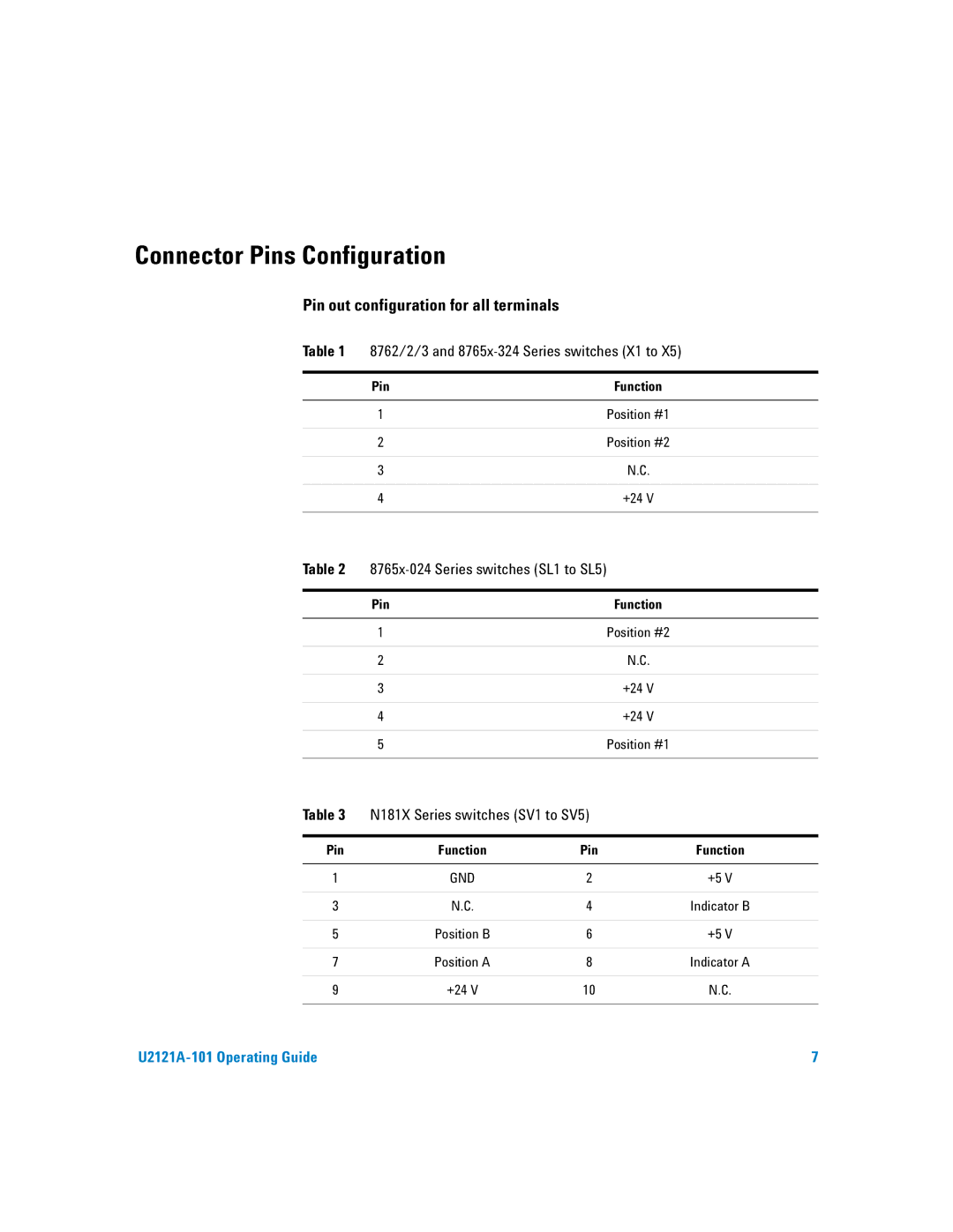
Table 1 | 8762/2/3 and | |
|
|
|
| Pin | Function |
|
|
|
| 1 | Position #1 |
|
|
|
| 2 | Position #2 |
|
|
|
| 3 | N.C. |
|
|
|
| 4 | +24 V |
|
|
|
Table 2 |
| |
|
|
|
| Pin | Function |
|
|
|
| 1 | Position #2 |
|
|
|
| 2 | N.C. |
|
|
|
| 3 | +24 V |
|
|
|
| 4 | +24 V |
|
|
|
| 5 | Position #1 |
|
|
|
Table 3 | N181X Series switches (SV1 to SV5) |
| |
|
|
|
|
Pin | Function | Pin | Function |
|
|
|
|
1 | GND | 2 | +5 V |
|
|
|
|
3 | N.C. | 4 | Indicator B |
|
|
|
|
5 | Position B | 6 | +5 V |
|
|
|
|
7 | Position A | 8 | Indicator A |
|
|
|
|
9 | +24 V | 10 | N.C. |
|
|
|
|
7 |