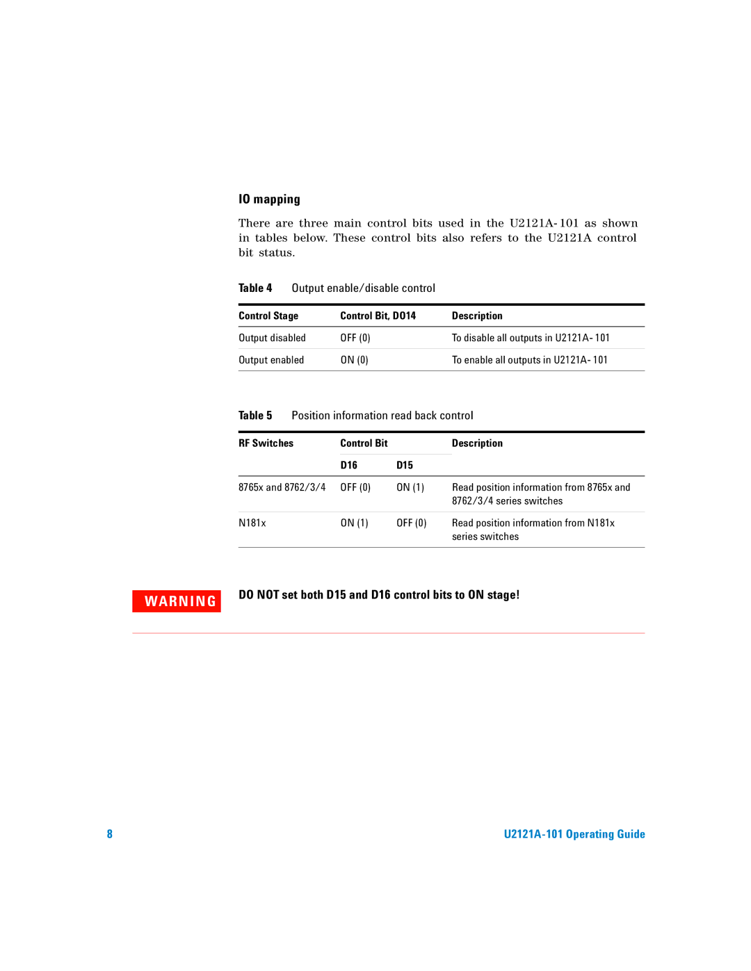
IO mapping
There are three main control bits used in the U2121A- 101 as shown in tables below. These control bits also refers to the U2121A control bit status.
Table 4 | Output enable/disable control |
| ||
|
|
| ||
Control Stage | Control Bit, DO14 | Description | ||
|
|
|
| |
Output disabled | OFF (0) |
| To disable all outputs in U2121A- 101 | |
|
|
|
| |
Output enabled | ON (0) |
| To enable all outputs in U2121A- 101 | |
|
|
| ||
Table 5 | Position information read back control | |||
|
|
|
| |
RF Switches | Control Bit |
| Description | |
|
|
|
|
|
|
| D16 | D15 |
|
|
|
|
| |
8765x and 8762/3/4 | OFF (0) | ON (1) | Read position information from 8765x and | |
|
|
|
| 8762/3/4 series switches |
|
|
|
|
|
N181x |
| ON (1) | OFF (0) | Read position information from N181x |
|
|
|
| series switches |
|
|
|
|
|
WA RN I N G | DO NOT set both D15 and D16 control bits to ON stage! |
|
8 |
|