![]()
![]()
![]()
![]() X7DBU/X7DGU User's Manual
X7DBU/X7DGU User's Manual
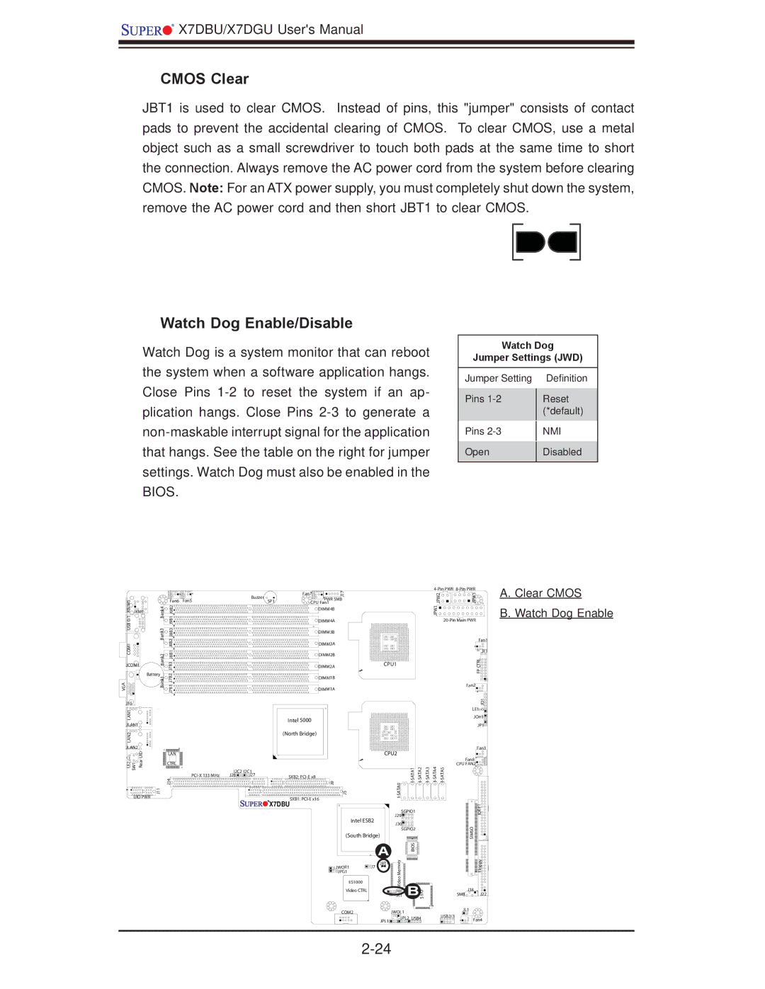
CMOS Clear
JBT1 is used to clear CMOS. Instead of pins, this "jumper" consists of contact pads to prevent the accidental clearing of CMOS. To clear CMOS, use a metal object such as a small screwdriver to touch both pads at the same time to short the connection. Always remove the AC power cord from the system before clearing CMOS. Note: For an ATX power supply, you must completely shut down the system, remove the AC power cord and then short JBT1 to clear CMOS.
Watch Dog Enable/Disable
Watch Dog is a system monitor that can reboot the system when a software application hangs. Close Pins
Watch Dog
Jumper Settings (JWD)
Jumper Setting |
| Definition |
Pins |
| Reset |
| ||
|
| (*default) |
Pins |
| NMI |
| ||
Open |
| Disabled |
| ||
|
|
|
|
|
|
|
|
|
|
| Fan7 | 17 |
|
|
|
|
| 2PW J |
| 3PW J |
|
|
|
|
|
| Buzzer |
|
| J |
|
|
|
|
|
| ||
KB/MS0/1 USBCOM1 |
|
| Fan6 | Fan5 |
| SP1 |
| PWR SMB |
|
|
|
|
|
| |||
| Bank4 Bank3 |
|
| CPU Fan1 |
|
|
|
|
|
|
| ||||||
| J9B1J9B2 J8B2J8B1J8B3 |
|
|
|
| DIMM4B |
|
|
|
|
|
| 1PW J |
|
| ||
JKM1 |
|
|
|
|
|
|
|
|
|
|
|
|
|
|
|
| |
|
|
|
|
|
|
|
| DIMM4A |
|
|
|
|
|
|
| ||
|
|
|
|
|
|
|
| DIMM3B |
|
|
|
|
|
|
|
|
|
|
|
|
|
|
|
|
| DIMM3A |
|
|
|
|
|
|
|
| Fan1 |
|
|
|
|
|
|
|
|
|
|
|
|
|
|
|
|
| |
|
| Bank2 |
|
|
|
|
| DIMM2B |
|
|
|
|
|
|
|
| JF1 |
|
| J7B3 |
|
|
|
|
|
|
|
|
|
|
|
| RLCTP | ||
JCOM1 |
|
|
|
| DIMM2A |
| CPU1 |
|
|
|
|
| |||||
|
|
|
|
|
|
|
|
|
|
|
|
|
|
|
|
| |
| Battery | J7B2 |
|
|
|
|
|
|
|
|
|
|
|
|
| F | |
VGA |
| Bank1 |
|
|
|
| DIMM1B |
|
|
|
|
|
|
|
| ||
| J7B1 |
|
|
|
|
|
|
|
|
|
|
|
|
| |||
|
|
|
|
| DIMM1A |
|
|
|
|
|
|
|
| Fan2 | |||
|
|
|
|
|
|
|
|
|
|
|
|
|
|
|
|
| |
J15 |
|
|
|
|
|
|
|
|
|
|
|
|
|
|
|
| 1DJ |
LAN1 |
|
|
|
|
|
|
|
|
|
|
|
|
|
|
|
| LE1 |
|
|
|
|
|
| Intel 5000 |
|
|
|
|
|
|
|
| JOH1 | ||
JLAN1 |
|
|
|
|
|
|
|
|
|
|
|
|
|
| JP1 | ||
|
|
|
|
|
|
|
|
|
|
|
|
|
|
|
| ||
LAN2 |
|
|
|
|
|
| (North Bridge) |
|
|
|
|
|
|
|
|
| |
|
|
|
|
|
|
|
|
|
|
|
|
|
|
|
|
| |
JLAN2 | UID |
|
|
|
|
|
|
|
|
|
|
|
|
|
|
| Fan3 |
|
| LAN |
|
|
|
|
|
| CPU2 |
|
|
|
|
|
| ||
LE2 SW1 | Rear |
| J14 |
|
|
|
| 9J |
|
| 0 | Fan8 | |||||
|
|
| CTRL |
|
|
|
|
|
|
|
|
|
|
|
| CPU FAN2 | |
|
|
|
| I2C2 | I2C1 |
|
|
|
|
|
|
|
|
|
|
| |
|
|
|
| J28 | J27 | SXB2: |
|
|
|
|
|
|
|
|
| ||
UIO PWR | J11 |
|
|
|
|
| SXB1: | 5J |
| ATA |
|
|
|
|
|
| |
|
|
|
|
|
| X7DBU |
|
|
|
|
|
|
|
|
| ||
|
|
|
|
|
|
|
|
|
|
|
|
|
|
| 1# | ||
|
|
|
|
|
|
|
|
|
|
| SGPIO1 |
|
|
|
| E | |
|
|
|
|
|
|
|
|
|
|
|
|
|
|
| ID | ||
|
|
|
|
|
|
|
|
|
|
| J29 |
|
|
|
|
| |
|
|
|
|
|
|
|
|
| Intel ESB2 |
|
|
|
|
|
| ||
|
|
|
|
|
|
|
|
| J30 |
|
|
|
|
|
| ||
|
|
|
|
|
|
|
|
|
|
|
|
|
|
|
| O | |
|
|
|
|
|
|
|
|
|
|
| SGPIO2 |
|
|
|
| ||
|
|
|
|
|
|
|
|
| (South Bridge) |
|
|
|
|
|
| SIM | |
|
|
|
|
|
|
|
|
|
|
|
|
|
|
|
|
| S |
|
|
|
|
|
|
|
|
|
| A |
| SIO B |
|
|
|
|
|
|
|
|
|
|
|
|
|
|
| yromeM |
|
|
|
|
| ypploF | |
|
|
|
|
|
|
|
|
| JWOR1 | JBT1 |
|
|
|
|
| ||
|
|
|
|
|
|
|
|
| J7 |
|
|
|
|
|
|
| |
|
|
|
|
|
|
|
|
| JPG1 |
|
|
|
|
|
|
|
|
|
|
|
|
|
|
|
|
| ES1000 |
| oe |
|
|
|
|
|
|
|
|
|
|
|
|
|
|
|
| Vid | BI/OS |
|
|
|
| ||
|
|
|
|
|
|
|
|
|
|
|
|
|
| J18 | |||
|
|
|
|
|
|
|
|
| Video CTRL |
| JWD |
|
|
| |||
|
|
|
|
|
|
|
|
|
|
| JK1 |
|
| SMB | J22 | ||
|
|
|
|
|
|
|
|
| COM2 | JWOL1 |
|
|
|
| JL1 | ||
|
|
|
|
|
|
|
|
|
|
|
|
| USB2/3 |
| |||
|
|
|
|
|
|
|
|
|
| JPL1 | JPL2 USB4 |
|
| Fan4 | |||
|
|
|
|
|
|
|
|
|
|
|
|
| |||||
|
|
|
|
|
|
|
|
|
|
|
|
|
|
|
| ||
|
|
|
|
|
|
|
|
|
|
|
|
|
|
|
| ||
A. Clear CMOS
B. Watch Dog Enable