![]()
![]()
![]()
![]() X7DBU/X7DGU User's Manual
X7DBU/X7DGU User's Manual
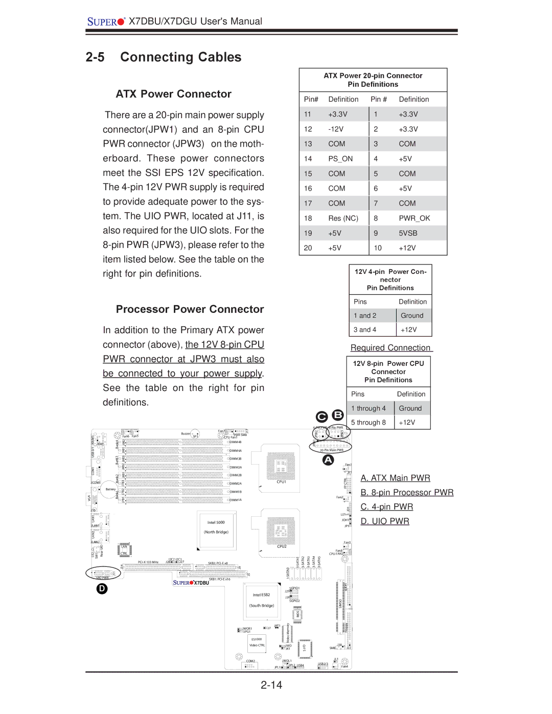
2-5 Connecting Cables
ATX Power 20-pin Connector
Pin Definitions
ATX Power Connector
There are a
Pin# Definition
11+3.3V
12
13COM
14PS_ON
15COM
16COM
17COM
18Res (NC)
19+5V
20+5V
Pin # Definition
1+3.3V
2+3.3V
3COM
4+5V
5COM
6+5V
7COM
8PWR_OK
95VSB
10+12V
right for pin definitions.
Processor Power Connector
12V
nector
Pin Definitions
Pins Definition
1 and 2 | Ground |
|
|
In addition to the Primary ATX power connector (above), the 12V
CB
3 and 4 | +12V |
|
|
Required Connection
12V 8-pin Power CPU
Connector
Pin Definitions
Pins |
| Definition |
1 through 4 |
| Ground |
| ||
5 through 8 |
| +12V |
|
|
|
|
|
|
| Fan7 | 17 |
|
|
|
|
|
| 2PW J |
| 3JPW |
|
|
|
|
| Buzzer |
|
| J |
|
|
|
|
|
|
| ||
KB/MS0/1 USBCOM1 |
| Fan6 | Fan5 |
|
| PWR SMB |
|
|
|
|
|
|
| ||||
|
| SP1 |
|
|
|
|
|
|
|
| |||||||
Bank4 Bank3 |
|
| CPU Fan1 |
|
|
|
|
|
|
|
| ||||||
J9B1J9B2 J8B2J8B1J8B3 |
|
|
|
| DIMM4B |
|
|
|
|
|
|
| 1PW J |
|
| ||
JKM1 |
|
|
|
|
|
|
|
|
|
|
|
|
|
|
|
|
|
|
|
|
|
|
|
| DIMM4A |
|
|
|
|
|
|
|
| ||
|
|
|
|
|
|
| DIMM3B |
|
|
|
|
|
|
|
| A |
|
|
|
|
|
|
|
| DIMM3A |
|
|
|
|
|
|
|
| Fan1 | |
| Bank2 |
|
|
|
|
| DIMM2B |
|
|
|
|
|
|
|
|
| JF1 |
| J7B3 |
|
|
|
|
|
|
|
|
|
|
|
|
| RLCTP | ||
JCOM1 |
|
|
|
| DIMM2A |
|
| CPU1 |
|
|
|
|
| ||||
|
|
|
|
|
|
|
|
|
|
|
|
|
| ||||
Battery | J7B2 |
|
|
|
|
|
|
|
|
|
|
|
|
|
| F | |
VGA | Bank1 |
|
|
|
| DIMM1B |
|
|
|
|
|
|
|
|
| ||
J7B1 |
|
|
|
|
|
|
|
|
|
|
|
|
|
| |||
|
|
|
| DIMM1A |
|
|
|
|
|
|
|
|
| Fan2 | |||
|
|
|
|
|
|
|
|
|
|
|
|
|
|
|
|
| |
J15 |
|
|
|
|
|
|
|
|
|
|
|
|
|
|
|
| 1DJ |
LAN1 |
|
|
|
|
|
|
|
|
|
|
|
|
|
|
|
| LE1 |
|
|
|
|
| Intel 5000 |
|
|
|
|
|
|
|
|
| JOH1 | ||
JLAN1 |
|
|
|
|
|
|
|
|
|
|
|
|
|
| JP1 | ||
|
|
|
|
|
|
|
|
|
|
|
|
|
|
|
| ||
LAN2 |
|
|
|
|
| (North Bridge) |
|
|
|
|
|
|
|
|
|
| |
|
|
|
|
|
|
|
|
|
|
|
|
|
|
|
|
| |
JLAN2 |
|
|
|
|
|
|
|
|
|
|
|
|
|
|
|
| Fan3 |
UID |
| LAN |
|
|
|
|
|
|
| CPU2 |
|
|
|
|
|
| |
|
|
|
|
|
|
|
|
|
|
|
|
|
|
| |||
LE2 SW1 Rear |
| J14 |
|
|
|
| 9J |
|
|
| 0 | Fan8 | |||||
|
| CTRL |
|
|
|
|
|
|
|
|
|
|
|
|
| CPU FAN2 | |
|
|
| I2C2 | I2C1 |
|
|
|
|
|
|
|
|
|
|
|
| |
|
|
| J28 | J27 | SXB2: |
|
|
|
|
|
|
|
|
|
| ||
|
|
|
|
|
|
|
|
|
|
|
|
|
|
|
| ||
UIO PWR | J11 |
|
|
|
|
| SXB1: | 5J |
|
| ATA |
|
|
|
|
|
|
|
|
|
|
| X7DBU |
|
|
|
|
|
|
|
|
|
| ||
D |
|
|
|
|
|
|
|
|
|
|
|
|
|
| 1# | ||
|
|
|
|
|
|
|
|
|
| SGPIO1 |
|
|
|
| E | ||
|
|
|
|
|
|
|
|
|
|
|
|
|
| ID | |||
|
|
|
|
|
|
|
|
|
| J29 |
|
|
|
|
| ||
|
|
|
|
|
|
| Intel ESB2 |
|
|
|
|
|
|
| |||
|
|
|
|
|
|
|
|
| J30 |
|
|
|
|
|
| ||
|
|
|
|
|
|
|
|
|
|
|
|
|
|
|
| O | |
|
|
|
|
|
|
|
|
|
|
| SGPIO2 |
|
|
|
| ||
|
|
|
|
|
|
|
| (South Bridge) |
|
|
|
|
|
|
| SIM | |
|
|
|
|
|
|
|
|
|
|
|
|
|
|
|
|
| S |
|
|
|
|
|
|
|
|
|
|
| yromeM | SIO B |
|
|
|
| ypploF |
|
|
|
|
|
|
|
| JWOR1 | J7 | JBT1 |
|
|
|
|
| ||
|
|
|
|
|
|
|
|
|
|
|
|
|
|
|
| ||
|
|
|
|
|
|
|
| JPG1 |
|
|
|
|
|
|
|
|
|
|
|
|
|
|
|
|
| ES1000 |
|
| oe |
|
|
|
|
|
|
|
|
|
|
|
|
|
|
|
| Vid |
|
|
|
|
|
| |
|
|
|
|
|
|
|
|
|
|
|
|
|
|
|
| J18 | |
|
|
|
|
|
|
|
| Video CTRL |
|
| JWD |
| I/O |
|
|
| |
|
|
|
|
|
|
|
|
|
|
| JK1 |
|
|
| SMB | J22 | |
|
|
|
|
|
|
|
|
|
|
|
|
| S |
|
|
|
|
|
|
|
|
|
|
|
| COM2 |
| JWOL1 |
|
|
|
| JL1 | ||
|
|
|
|
|
|
|
|
|
|
|
|
| USB2/3 |
| |||
|
|
|
|
|
|
|
|
|
| JPL1 | JPL2 | USB4 |
|
| Fan4 | ||
|
|
|
|
|
|
|
|
|
|
|
|
| |||||
|
|
|
|
|
|
|
|
|
|
|
|
|
|
|
| ||
|
|
|
|
|
|
|
|
|
|
|
|
|
|
| |||
A. ATX Main PWR
B.
C.
D.UIO PWR