| Chapter 2: Installation |
|
|
|
|
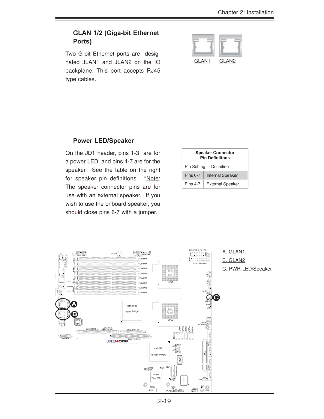
GLAN 1/2 |
|
Ports) |
|
Two |
|
nated JLAN1 and JLAN2 on the IO | GLAN1 GLAN2 |
backplane. This port accepts RJ45 |
|
type cables. |
|
Power LED/Speaker
On the JD1 header, pins
apower LED, and pins
Speaker Connector
Pin Definitions
Pin Setting | Definition | |
|
| |
Pins |
| Internal Speaker |
|
|
|
Pins |
| External Speaker |
|
|
|
|
|
|
|
|
|
|
| Fan7 | 17 |
|
|
|
|
| 2PW J |
| 3PW J |
|
|
|
|
|
| Buzzer |
|
| J |
|
|
|
|
|
| ||
KB/MS0/1 USBCOM1 |
|
| Fan6 | Fan5 |
|
| PWR SMB |
|
|
|
|
|
| ||||
|
|
| SP1 |
|
|
|
|
|
|
| |||||||
| Bank4 Bank3 |
|
| CPU Fan1 |
|
|
|
|
|
|
| ||||||
| J9B1J9B2 J8B2J8B3J8B1 |
|
|
|
| DIMM4B |
|
|
|
|
|
| 1JPW |
|
| ||
JKM1 |
|
|
|
|
|
|
|
|
|
|
|
|
|
|
|
| |
|
|
|
|
|
|
|
| DIMM4A |
|
|
|
|
|
|
| ||
|
|
|
|
|
|
|
| DIMM3B |
|
|
|
|
|
|
|
|
|
|
|
|
|
|
|
|
| DIMM3A |
|
|
|
|
|
|
|
| Fan1 |
|
|
|
|
|
|
|
|
|
|
|
|
|
|
|
|
| |
|
| Bank2 |
|
|
|
|
| DIMM2B |
|
|
|
|
|
|
|
| JF1 |
|
| J7B3 |
|
|
|
|
|
|
|
|
|
|
|
| RLCTP | ||
JCOM1 |
|
|
|
| DIMM2A |
| CPU1 |
|
|
|
|
| |||||
| Battery | J7B2 |
|
|
|
|
|
|
|
|
|
|
|
|
| F | |
VGA |
| Bank1 |
|
|
|
| DIMM1B |
|
|
|
|
|
|
|
| ||
| J7B1 |
|
|
|
|
|
|
|
|
|
|
|
|
| |||
|
|
|
|
| DIMM1A |
|
|
|
|
|
|
|
| Fan2 | |||
|
|
|
|
|
|
|
|
|
|
|
|
|
|
|
|
| |
J15 |
|
|
|
|
|
|
|
|
|
|
|
|
|
|
|
| 1DJ |
LAN1 |
| A |
|
|
|
|
|
|
|
|
|
|
|
|
| LE1 | |
|
|
|
| Intel 5000 |
|
|
|
|
|
|
|
| JOH1 | ||||
JLAN1 |
|
|
|
|
|
|
|
|
|
|
|
| JP1 | ||||
|
|
|
|
|
|
|
|
|
|
|
|
|
|
|
| ||
LAN2 |
| B |
|
|
| (North Bridge) |
|
|
|
|
|
|
|
|
| ||
|
|
|
|
|
|
|
|
|
|
|
|
|
|
| |||
JLAN2 | UID |
|
|
|
|
|
|
|
|
|
|
|
|
| Fan3 | ||
|
| LAN |
|
|
|
|
|
| CPU2 |
|
|
|
|
|
| ||
|
|
|
|
|
|
|
|
|
|
|
|
|
|
| |||
LE2 SW1 | Rear |
| J14 |
|
|
|
| 9J |
|
| 0 | Fan8 | |||||
|
|
| CTRL |
|
|
|
|
|
|
|
|
|
|
|
| CPU FAN2 | |
|
|
|
| I2C2 | I2C1 |
|
|
|
|
|
|
|
|
|
|
| |
|
|
|
| J28 | J27 | SXB2: |
|
|
|
|
|
|
|
|
| ||
UIO PWR | J11 |
|
|
|
|
| SXB1: | 5J |
| ATA |
|
|
|
|
|
| |
|
|
|
|
|
| X7DBU |
|
|
|
|
|
|
|
|
| ||
|
|
|
|
|
|
|
|
|
|
|
|
|
|
| 1# | ||
|
|
|
|
|
|
|
|
|
|
| SGPIO1 |
|
|
|
| E | |
|
|
|
|
|
|
|
|
|
|
|
|
|
|
| ID | ||
|
|
|
|
|
|
|
|
|
|
| J29 |
|
|
|
|
| |
|
|
|
|
|
|
|
|
| Intel ESB2 |
|
|
|
|
|
| ||
|
|
|
|
|
|
|
|
| J30 |
|
|
|
|
|
| ||
|
|
|
|
|
|
|
|
|
|
|
|
|
|
|
| O | |
|
|
|
|
|
|
|
|
|
|
| SGPIO2 |
|
|
|
| ||
|
|
|
|
|
|
|
|
| (South Bridge) |
|
|
|
|
|
| SIM | |
|
|
|
|
|
|
|
|
|
|
|
|
|
|
|
|
| S |
|
|
|
|
|
|
|
|
|
|
| yromeM | SIO B |
|
|
|
| ypploF |
|
|
|
|
|
|
|
|
| JWOR1 | JBT1 |
|
|
|
|
| ||
|
|
|
|
|
|
|
|
| J7 |
|
|
|
|
|
|
| |
|
|
|
|
|
|
|
|
| JPG1 |
|
|
|
|
|
|
|
|
|
|
|
|
|
|
|
|
| ES1000 |
| oe |
|
|
|
|
|
|
|
|
|
|
|
|
|
|
|
| Vid |
|
|
|
|
|
| |
|
|
|
|
|
|
|
|
|
|
|
|
|
|
|
| J18 | |
|
|
|
|
|
|
|
|
| Video CTRL |
| JWD |
| I/O |
|
|
| |
|
|
|
|
|
|
|
|
|
|
| JK1 |
|
|
| SMB | J22 | |
|
|
|
|
|
|
|
|
|
|
|
|
| S |
|
|
|
|
|
|
|
|
|
|
|
|
| COM2 | JWOL1 |
|
|
|
| JL1 | ||
|
|
|
|
|
|
|
|
|
|
|
|
| USB2/3 |
| |||
|
|
|
|
|
|
|
|
|
| JPL1 | JPL2 | USB4 |
|
| Fan4 | ||
|
|
|
|
|
|
|
|
|
|
|
|
| |||||
|
|
|
|
|
|
|
|
|
|
|
|
|
|
|
| ||
|
|
|
|
|
|
|
|
|
|
|
|
|
|
|
| ||
C
A.GLAN1
B.GLAN2
C.PWR LED/Speaker