![]()
![]()
![]()
![]() X7DBU/X7DGU User's Manual
X7DBU/X7DGU User's Manual
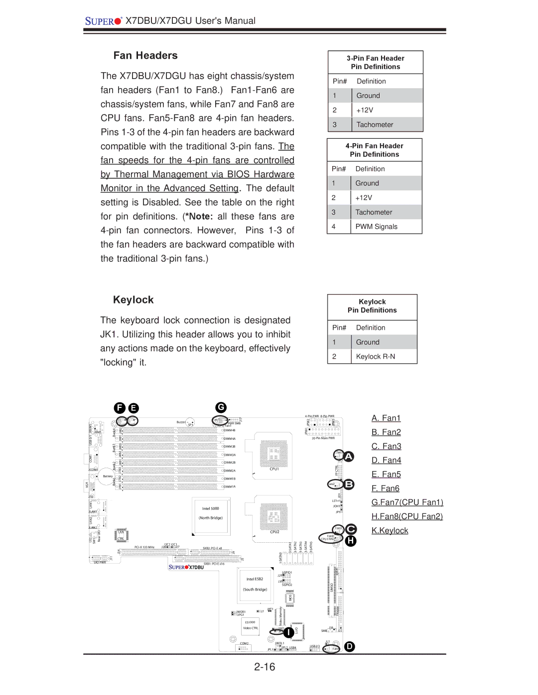
Fan Headers
The X7DBU/X7DGU has eight chassis/system fan headers (Fan1 to Fan8.)
3-Pin Fan Header
Pin Definitions
Pin# Definition
1Ground
2+12V
3Tachometer
Pin Definitions
Pin# Definition
1Ground
2+12V
3Tachometer
4PWM Signals
Keylock
The keyboard lock connection is designated JK1. Utilizing this header allows you to inhibit any actions made on the keyboard, effectively "locking" it.
Keylock
Pin Definitions
Pin# Definition
1Ground
2Keylock R-N
|
|
| F | E |
|
|
| G |
|
|
|
|
|
|
|
|
|
|
|
|
|
| Fan7 | 17 |
|
|
|
|
|
|
|
|
|
|
| Buzzer |
|
| J |
|
|
|
|
|
KB/MS0/1 USBCOM1 |
|
| Fan6 | Fan5 |
|
| PWR SMB |
|
|
|
|
| ||
|
|
| SP1 |
|
|
|
|
|
| |||||
| Bank4 Bank3 |
|
| CPU Fan1 |
|
|
|
|
|
| ||||
| J9B1J9B2 J8B2J8B1J8B3 |
|
|
|
| DIMM4B |
|
|
|
|
|
| ||
JKM1 |
|
|
|
|
|
|
|
|
|
|
|
|
| |
|
|
|
|
|
|
|
| DIMM4A |
|
|
|
|
|
|
|
|
|
|
|
|
|
| DIMM3B |
|
|
|
|
|
|
|
|
|
|
|
|
|
| DIMM3A |
|
|
|
|
|
|
|
| Bank2 | J7B3 |
|
|
|
| DIMM2B |
|
|
|
|
|
|
JCOM1 |
|
|
|
| DIMM2A |
| CPU1 |
|
|
| ||||
|
|
|
|
|
|
|
|
|
| |||||
| Battery | J7B2 |
|
|
|
|
|
|
|
|
|
|
| |
|
| Bank1 |
|
|
|
| DIMM1B |
|
|
|
|
|
| |
|
| J7B1 |
|
|
|
|
|
|
|
|
|
| ||
VGA |
|
|
|
|
| DIMM1A |
|
|
|
|
|
| ||
J15 |
|
|
|
|
|
|
|
|
|
|
|
|
|
|
LAN1 |
|
|
|
|
|
| Intel 5000 |
|
|
|
|
|
| |
JLAN1 |
|
|
|
|
|
|
|
|
|
|
|
| ||
|
|
|
|
|
|
|
|
|
|
|
|
|
| |
LAN2 |
|
|
|
|
|
| (North Bridge) |
|
|
|
|
|
| |
|
|
|
|
|
|
|
|
|
|
|
|
|
| |
JLAN2 | UID |
|
|
|
|
|
|
|
|
|
|
|
|
|
|
| LAN |
|
|
|
|
|
| CPU2 |
|
|
| ||
LE2 SW1 | Rear |
|
|
|
|
|
|
| ||||||
| J14 |
|
|
|
| 9J |
|
| 0 | |||||
|
|
| CTRL |
|
|
|
|
|
|
|
|
|
|
|
|
|
|
| I2C2 | I2C1 |
|
|
|
|
|
|
|
| |
|
|
|
| J28 | J27 | SXB2: |
|
|
|
|
|
| ||
UIO PWR | J11 |
|
|
|
|
| SXB1: | 5J |
| ATA |
|
|
| |
|
|
|
|
|
| X7DBU |
|
|
|
|
|
| ||
|
|
|
|
|
|
|
|
|
|
|
|
| ||
|
|
|
|
|
|
|
|
|
|
| SGPIO1 |
|
| |
|
|
|
|
|
|
|
|
| Intel ESB2 | J29 |
|
|
| |
|
|
|
|
|
|
|
|
| J30 |
|
|
| ||
|
|
|
|
|
|
|
|
|
|
|
|
|
| |
|
|
|
|
|
|
|
|
|
|
| SGPIO2 |
|
| |
|
|
|
|
|
|
|
|
| (South Bridge) |
|
|
|
| |
|
|
|
|
|
|
|
|
|
|
|
| SIO B |
|
|
|
|
|
|
|
|
|
|
|
| JBT1 | yro |
|
|
|
|
|
|
|
|
|
|
|
| JWOR1 | J7 | m |
|
|
|
|
|
|
|
|
|
|
|
| JPG1 |
| e |
|
|
|
|
|
|
|
|
|
|
|
| ES1000 |
| Moe |
|
|
|
|
|
|
|
|
|
|
|
|
| Vid |
|
|
| |
|
|
|
|
|
|
|
|
|
|
|
|
|
| |
|
|
|
|
|
|
|
|
| Video CTRL |
| JWD | I | I/O |
|
|
|
|
|
|
|
|
|
|
|
| JK1 |
| ||
|
|
|
|
|
|
|
|
|
|
|
| S |
| |
|
|
|
|
|
|
|
|
| COM2 |
| JWOL1 |
|
|
|
|
|
|
|
|
|
|
|
|
| JPL1 | JPL2 USB4 |
| ||
|
|
|
|
|
|
|
|
|
|
|
|
|
| |
|
|
|
|
|
|
|
|
|
|
|
| |||
| ||
2PW J | 3JPW |
|
1PW J |
|
|
|
| |
| Fan1 | A |
| JF1 | |
| RLCT PF | B |
| Fan2 | |
| 1DJ |
|
| LE1 |
|
| JOH1 |
|
| JP1 |
|
| Fan3 | C |
| Fan8 | H |
4AT AS- I | CPU FAN2 | |
5AT AS- I |
| |
| 1#E ID |
|
| OSIM S |
|
| ypp loF |
|
| J18 |
SMB | J22 |
JL1 | D |
USB2/3 | |
Fan4 |
A.Fan1
B.Fan2
C.Fan3
D.Fan4
E.Fan5
F.Fan6 G.Fan7(CPU Fan1) H.Fan8(CPU Fan2) K.Keylock