|
|
| Chapter 1: Introduction | ||
|
|
|
| ||
|
|
|
| ||
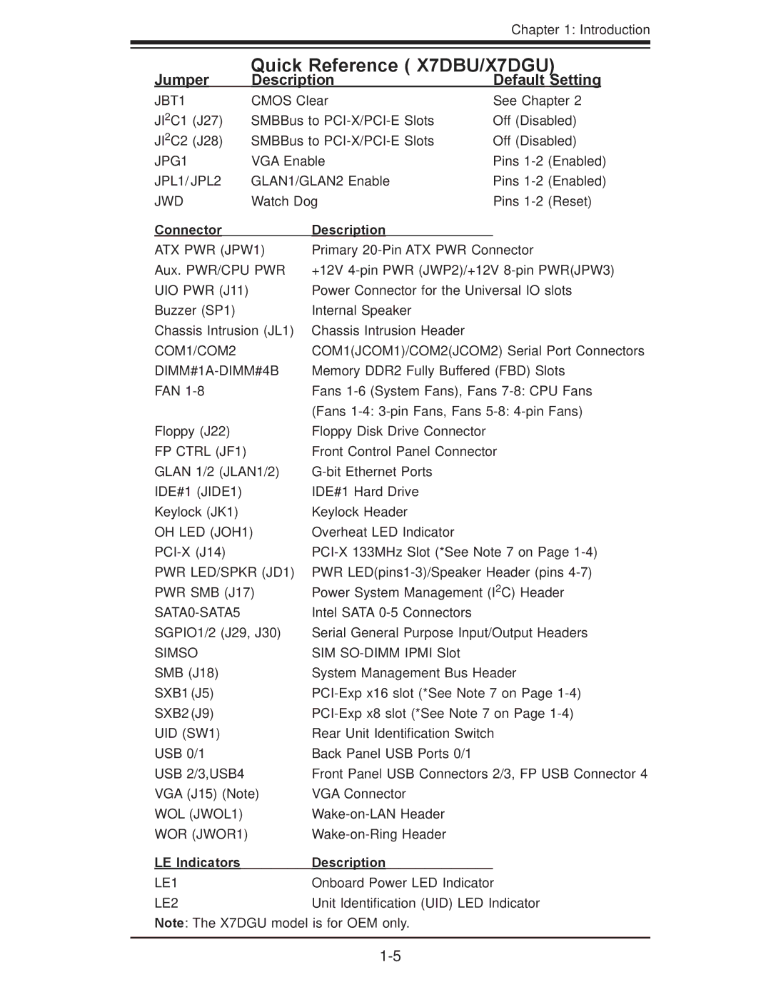
Jumper | Quick Reference ( X7DBU/X7DGU) | ||||
Description | Default Setting | ||||
|
|
|
|
| |
JBT1 | CMOS Clear | See Chapter 2 | |||
JI2C1 (J27) | SMBBus to | Off (Disabled) | |||
JI2C2 (J28) | SMBBus to | Off (Disabled) | |||
JPG1 | VGA Enable | Pins | (Enabled) | ||
JPL1/ JPL2 | GLAN1/GLAN2 Enable | Pins | (Enabled) | ||
JWD | Watch Dog | Pins | (Reset) | ||
Connector |
| Description |
|
|
ATX PWR (JPW1) | Primary | |||
Aux. PWR/CPU PWR | +12V | |||
UIO PWR (J11) | Power Connector for the Universal IO slots | |||
Buzzer (SP1) | Internal Speaker | |||
Chassis Intrusion (JL1) | Chassis Intrusion Header | |||
COM1/COM2 | COM1(JCOM1)/COM2(JCOM2) Serial Port Connectors | |||
| Memory DDR2 Fully Buffered (FBD) Slots | |||
FAN | Fans | |||
|
| (Fans | ||
Floppy (J22) | Floppy Disk Drive Connector | |||
FP CTRL (JF1) | Front Control Panel Connector | |||
GLAN 1/2 (JLAN1/2) | ||||
IDE#1 (JIDE1) | IDE#1 Hard Drive | |||
Keylock (JK1) | Keylock Header | |||
OH LED (JOH1) | Overheat LED Indicator | |||
PWR LED/SPKR (JD1) | PWR | |||
PWR SMB (J17) | Power System Management (I2C) Header | |||
Intel SATA | ||||
SGPIO1/2 (J29, J30) | Serial General Purpose Input/Output Headers | |||
SIMSO | SIM | |||
SMB (J18) | System Management Bus Header | |||
SXB1 (J5) | ||||
SXB2 (J9) | ||||
UID (SW1) | Rear Unit Identification Switch | |||
USB 0/1 | Back Panel USB Ports 0/1 | |||
USB 2/3,USB4 | Front Panel USB Connectors 2/3, FP USB Connector 4 | |||
VGA (J15) (Note) | VGA Connector | |||
WOL (JWOL1) | ||||
WOR (JWOR1) | ||||
LE Indicators | Description | |||
|
|
|
|
|
LE1 |
| Onboard Power LED Indicator | ||
LE2 |
| Unit Identification (UID) LED Indicator | ||
Note: The X7DGU model is for OEM only.
