Chapter 2: Installation
Universal Serial Bus (USB)
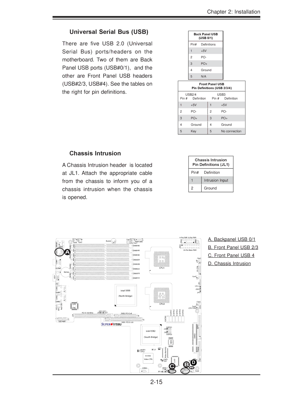
There are five USB 2.0 (Universal Serial Bus) ports/headers on the motherboard. Two of them are Back Panel USB ports (USB#0/1), and the other are Front Panel USB headers (USB#2/3, USB#4). See the tables on the right for pin definitions.
Back Panel USB
(USB 0/1)
Pin# Definitions
1+5V
2PO-
3PO+
4Ground
5N/A
Front Panel USB
Pin Definitions (USB 2/3/4)
USB2/4
Pin # Definition
1+5V
2PO-
3PO+
4Ground
5Key
USB3
Pin # Definition
1+5V
2PO-
3PO+
4Ground
5No connection
Chassis Intrusion
A Chassis Intrusion header is located at JL1. Attach the appropriate cable from the chassis to inform you of a chassis intrusion when the chassis is opened.
Chassis Intrusion
Pin Definitions (JL1)
Pin# Definition
1Intrusion Input
2Ground
|
|
|
|
|
| Buzzer |
| PWR SMB |
|
|
|
|
|
| A. Backpanel USB 0/1 | |||
|
|
|
|
|
|
|
| Fan7 | J17 |
|
|
|
|
| 2PWJ | 3PWJ |
|
|
|
|
|
|
|
|
|
|
|
|
|
|
|
|
|
| |||
KB/MS0/1 USBCOM1 |
| Bank3 | Fan6 | Fan5 |
| SP1 |
| CPU Fan1 |
|
|
|
|
|
|
| D. Chassis Intrusion | ||
| J9B1J9B2 J8B2J8B1J8B3 |
|
|
|
|
|
|
|
|
|
|
| 1JPW |
|
| |||
JKM1 | Bank4 |
|
|
|
|
| DIMM4B |
|
|
|
|
|
|
|
|
| B. Front Panel USB 2/3 | |
| A |
|
|
|
|
| DIMM4A |
|
|
|
|
|
|
|
| C. Front Panel USB 4 | ||
|
|
|
|
|
| DIMM3B |
|
|
|
|
|
|
|
| Fan1 | |||
|
|
|
|
|
|
|
|
|
|
|
|
|
|
|
| |||
|
|
|
|
|
|
|
| DIMM3A |
|
|
|
|
|
|
|
|
|
|
|
| Bank2 |
|
|
|
|
| DIMM2B |
|
|
|
|
|
|
|
| JF1 |
|
|
| J7B3 |
|
|
|
|
|
|
|
|
|
|
|
| RLCTP |
| ||
JCOM1 |
|
|
|
| DIMM2A |
| CPU1 |
|
|
|
|
|
| |||||
|
|
|
|
|
|
|
|
|
|
|
|
|
|
|
|
|
| |
| Battery | J7B2 |
|
|
|
|
|
|
|
|
|
|
|
|
| F |
| |
VGA |
| Bank1 |
|
|
|
| DIMM1B |
|
|
|
|
|
|
|
|
| ||
| J7B1 |
|
|
|
|
|
|
|
|
|
|
|
|
|
| |||
|
|
|
|
| DIMM1A |
|
|
|
|
|
|
| Fan2 |
|
| |||
|
|
|
|
|
|
|
|
|
|
|
|
|
|
|
|
|
| |
J15 |
|
|
|
|
|
|
|
|
|
|
|
|
|
|
|
| 1DJ |
|
LAN1 |
|
|
|
|
|
|
|
|
|
|
|
|
|
|
| LE1 |
| |
|
|
|
|
|
| Intel 5000 |
|
|
|
|
|
|
| JOH1 |
| |||
JLAN1 |
|
|
|
|
|
|
|
|
|
|
|
|
|
| JP1 |
| ||
|
|
|
|
|
|
|
|
|
|
|
|
|
|
|
|
| ||
LAN2 |
|
|
|
|
|
| (North Bridge) |
|
|
|
|
|
|
|
|
|
| |
|
|
|
|
|
|
|
|
|
|
|
|
|
|
|
|
|
| |
JLAN2 | UID |
|
|
|
|
|
|
|
|
|
|
|
|
|
|
| Fan3 |
|
|
| LAN |
|
|
|
|
|
| CPU2 |
|
|
|
|
|
|
| ||
LE2 SW1 | Rear |
| J14 |
|
|
|
| 9J |
|
| 0 | Fan8 |
|
| ||||
|
|
|
|
|
|
|
|
| ||||||||||
|
|
| CTRL |
|
|
|
|
|
|
|
|
|
|
|
| CPU FAN2 |
|
|
|
|
|
| I2C2 | I2C1 |
|
|
|
|
|
|
|
|
|
|
|
| |
|
|
|
| J28 | J27 | SXB2: |
|
|
|
|
|
|
|
|
|
| ||
UIO PWR | J11 |
|
|
|
|
| SXB1: | 5J |
| ATA |
|
|
|
|
|
|
| |
|
|
|
|
|
| X7DBU |
|
|
|
|
|
|
|
|
|
| ||
|
|
|
|
|
|
|
|
|
|
|
|
|
|
| 1# |
| ||
|
|
|
|
|
|
|
|
|
|
| SGPIO1 |
|
|
|
| E |
| |
|
|
|
|
|
|
|
|
|
|
|
|
|
|
| ID |
| ||
|
|
|
|
|
|
|
|
|
|
| J29 |
|
|
|
|
|
| |
|
|
|
|
|
|
|
|
| Intel ESB2 |
|
|
|
|
|
|
| ||
|
|
|
|
|
|
|
|
| J30 |
|
|
|
|
|
|
| ||
|
|
|
|
|
|
|
|
|
|
|
|
|
|
| O |
|
| |
|
|
|
|
|
|
|
|
|
|
| SGPIO2 |
|
|
|
|
| ||
|
|
|
|
|
|
|
|
| (South Bridge) |
|
|
|
|
| SIM |
|
| |
|
|
|
|
|
|
|
|
|
|
|
|
|
|
|
| S |
|
|
|
|
|
|
|
|
|
|
|
|
| yromeM | SIO B |
|
|
|
| ypploF |
|
|
|
|
|
|
|
|
|
| JWOR1 | JBT1 |
|
|
|
|
|
| ||
|
|
|
|
|
|
|
|
| J7 |
|
|
|
|
|
|
|
| |
|
|
|
|
|
|
|
|
| JPG1 |
|
|
|
|
|
|
|
|
|
|
|
|
|
|
|
|
|
| ES1000 |
| oe |
|
|
|
|
|
|
|
|
|
|
|
|
|
|
|
|
| Vid |
|
|
|
|
|
|
| |
|
|
|
|
|
|
|
|
|
|
|
|
|
|
| J18 |
|
| |
|
|
|
|
|
|
|
|
| Video CTRL |
| JWD |
| I/O |
|
|
|
| |
|
|
|
|
|
|
|
|
|
|
|
|
|
|
| D | J22 |
| |
|
|
|
|
|
|
|
|
|
|
| JK1 |
|
|
| SMB |
| ||
|
|
|
|
|
|
|
|
|
|
|
|
| S |
|
| B JL1 |
|
|
|
|
|
|
|
|
|
|
| COM2 | JWOL1 | C |
|
|
|
| |||
|
|
|
|
|
|
|
|
|
|
| USB2/3 |
|
| |||||
|
|
|
|
|
|
|
|
|
| JPL1 | JPL2 USB4 |
|
| Fan4 |
| |||
|
|
|
|
|
|
|
|
|
|
|
|
|
|
|
|
| ||