Chapter 2: Installation
B. Front Control Panel
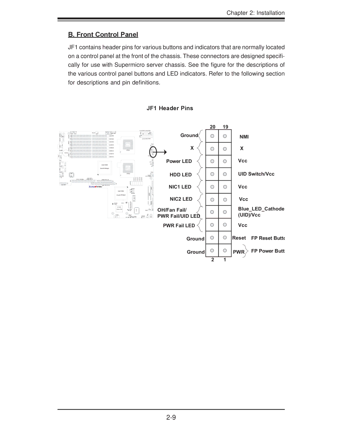
JF1 contains header pins for various buttons and indicators that are normally located on a control panel at the front of the chassis. These connectors are designed specifi- cally for use with Supermicro server chassis. See the figure for the descriptions of the various control panel buttons and LED indicators. Refer to the following section for descriptions and pin definitions.
JF1 Header Pins
S | Bank4 Bank3 | Fan6 | Fan5 |
KB/M0/1 COM1USB | J9B1J9B2 J8B2J8B3J8B1 |
| |
JKM1 |
|
|
|
JCOM1 | Bank2 | J7B3 |
|
| Battery | J7B2 | |
VGA | Bank1 | ||
J7B1 | |||
J15 |
|
| |
LAN1 |
|
| |
JLAN1 |
|
| |
LAN2 |
|
| |
JLAN2 | UID |
| |
| LAN | ||
LE2 SW1 | Rear | CTRL | |
|
| ||
|
| J14 | |
| J11 |
| |
UIO PWR |
| ||
| Buzzer | Fan7 | J17 |
|
|
|
|
| PWR SMB |
|
|
|
| ||
| SP1 | CPU Fan1 |
|
|
|
|
|
|
| DIMM4B |
|
|
|
|
|
|
| DIMM4A |
|
|
|
|
|
|
| DIMM3B |
|
|
|
|
|
|
| DIMM3A |
|
|
|
|
|
|
| DIMM2B |
|
|
|
|
|
|
| DIMM2A |
| CPU1 |
|
| |
|
| DIMM1B |
|
|
|
|
|
|
| DIMM1A |
|
|
|
|
|
|
| Intel 5000 |
|
|
|
|
|
|
| (North Bridge) |
|
|
|
|
|
|
|
|
| CPU2 |
|
| |
I2C2 | I2C1 | J9 | J5 |
| SATA0 | ||
J28 | J27 | SXB2: |
|
|
|
|
|
|
| SXB1: |
|
|
|
| |
|
|
|
|
|
|
| |
| X7DBU |
|
|
|
|
| |
|
|
|
|
| SGPIO1 |
| |
|
|
| Intel ESB2 | J29 |
|
| |
|
|
| J30 |
|
| ||
|
|
|
|
|
|
| |
|
|
|
|
| SGPIO2 |
| |
|
|
| (South Bridge) |
|
|
| |
|
|
|
|
|
| BIOS |
|
|
|
| JWOR1 | JBT1 | ory |
|
|
|
|
| J7 | em |
|
| |
|
|
| JPG1 |
|
|
| |
|
|
|
|
| M |
|
|
|
|
| ES1000 |
| Video |
|
|
|
|
| Video CTRL |
| JWD |
| I/OS |
|
|
|
|
| JK1 |
| |
|
|
| COM2 |
| JWOL1 |
|
|
|
|
|
| JPL1 | JPL2 | USB4 | |
|
|
|
|
|
|
| |
| ||
2JPW | 3JPW |
|
1JPW |
|
|
|
| |
|
| Fan1 |
|
| JF1 |
|
| CTRLFP |
| Fan2 |
|
|
| JD1 |
| LE1 | |
| JOH1 | |
|
| JP1 |
|
| Fan3 |
| Fan8 |
|
CPU FAN2 |
| |
| ||
|
| E#1ID |
| SIMSO |
|
|
| Floppy |
| J18 | J22 |
| SMB | |
| JL1 |
|
| USB2/3 |
|
| Fan4 | |
Ground
X
Power LED
HDD LED
NIC1 LED
NIC2 LED
OH/Fan Fail/ PWR Fail/UID LED
PWR Fail LED
Ground
Ground
20 | 19 |
| NMI |
| X |
| Vcc |
UID Switch/Vcc
Vcc
Vcc
Blue_LED_Cathode (UID)/Vcc
Vcc
Reset | FP Reset Butto |
PWR | FP Power Butt |
2 1