Chapter 2: Installation
2-6 Jumper Settings
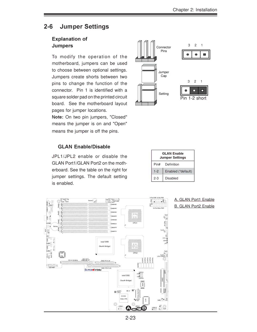
Explanation of
Jumpers
To modify the operation of the motherboard, jumpers can be used to choose between optional settings. Jumpers create shorts between two pins to change the function of the connector. Pin 1 is identified with a square solder pad on the printed circuit board. See the motherboard layout pages for jumper locations.
Note: On two pin jumpers, "Closed" means the jumper is on and "Open" means the jumper is off the pins.
Connector
Pins
Jumper
Cap
Setting
3 2 1
3 2 1
Pin
GLAN Enable/Disable
JPL1/JPL2 enable or disable the GLAN Port1/GLAN Port2 on the moth- erboard. See the table on the right for jumper settings. The default setting is enabled.
GLAN Enable
Jumper Settings
Pin# |
| Definition |
| Enabled (*default) | |
| ||
| Disabled | |
| ||
|
|
|
|
|
|
|
|
| Buzzer |
| Fan7 | J17 |
|
|
|
|
|
|
| 2PW J |
| 3PW J |
|
|
|
|
|
|
|
|
|
|
|
|
|
|
|
| ||||
KB/MS0/1 USBCOM1 |
|
| Fan6 | Fan5 |
|
| PWR SMB |
|
|
|
|
|
|
|
| ||||
|
|
| SP1 |
|
|
|
|
|
|
|
|
| |||||||
| Bank4 Bank3 |
|
| CPU Fan1 |
|
|
|
|
|
|
|
|
| ||||||
| J9B1J9B2 J8B2J8B1J8B3 |
|
|
|
| DIMM4B |
|
|
|
|
|
|
|
| 1JPW |
|
| ||
JKM1 |
|
|
|
|
|
|
|
|
|
|
|
|
|
|
|
|
|
| |
|
|
|
|
|
|
|
| DIMM4A |
|
|
|
|
|
|
|
|
| ||
|
|
|
|
|
|
|
| DIMM3B |
|
|
|
|
|
|
|
|
|
|
|
|
|
|
|
|
|
|
| DIMM3A |
|
|
|
|
|
|
|
|
|
| Fan1 |
|
|
|
|
|
|
|
|
|
|
|
|
|
|
|
|
|
|
| |
|
| Bank2 |
|
|
|
|
| DIMM2B |
|
|
|
|
|
|
|
|
|
| JF1 |
|
| J7B3 |
|
|
|
|
|
|
|
|
|
|
|
|
|
| RLCTP | ||
JCOM1 |
|
|
|
| DIMM2A |
|
|
| CPU1 |
|
|
|
|
| |||||
|
|
|
|
|
|
|
|
|
|
|
|
|
|
|
|
|
|
| |
| Battery | J7B2 |
|
|
|
|
|
|
|
|
|
|
|
|
|
|
| F | |
VGA |
| Bank1 |
|
|
|
| DIMM1B |
|
|
|
|
|
|
|
|
|
| ||
| J7B1 |
|
|
|
|
|
|
|
|
|
|
|
|
|
|
| |||
|
|
|
|
| DIMM1A |
|
|
|
|
|
|
|
|
|
| Fan2 | |||
|
|
|
|
|
|
|
|
|
|
|
|
|
|
|
|
|
|
| |
J15 |
|
|
|
|
|
|
|
|
|
|
|
|
|
|
|
|
|
| 1DJ |
LAN1 |
|
|
|
|
|
|
|
|
|
|
|
|
|
|
|
|
|
| LE1 |
|
|
|
|
|
| Intel 5000 |
|
|
|
|
|
|
|
|
|
| JOH1 | ||
JLAN1 |
|
|
|
|
|
|
|
|
|
|
|
|
|
|
|
| JP1 | ||
|
|
|
|
|
|
|
|
|
|
|
|
|
|
|
|
|
| ||
LAN2 |
|
|
|
|
|
| (North Bridge) |
|
|
|
|
|
|
|
|
|
|
| |
|
|
|
|
|
|
|
|
|
|
|
|
|
|
|
|
|
|
| |
JLAN2 | UID |
|
|
|
|
|
|
|
|
|
|
|
|
|
|
|
|
| Fan3 |
|
| LAN |
|
|
|
|
|
|
|
| CPU2 |
|
|
|
|
|
| ||
LE2 SW1 | Rear |
| J14 |
|
|
|
| 9J |
|
|
|
| 0 | Fan8 | |||||
|
|
| CTRL |
|
|
|
|
|
|
|
|
|
|
|
|
|
| CPU FAN2 | |
|
|
|
| I2C2 | I2C1 |
|
|
|
|
|
|
|
|
|
|
|
|
| |
|
|
|
| J28 | J27 | SXB2: |
|
|
|
|
|
|
|
|
|
|
| ||
UIO PWR | J11 |
|
|
|
|
| SXB1: | 5J |
|
|
| ATA |
|
|
|
|
|
| |
|
|
|
|
|
| X7DBU |
|
|
|
|
|
|
|
|
|
|
| ||
|
|
|
|
|
|
|
|
|
|
|
|
|
|
|
|
| 1# | ||
|
|
|
|
|
|
|
|
|
|
|
|
| SGPIO1 |
|
|
|
| E | |
|
|
|
|
|
|
|
|
|
|
|
|
|
|
|
|
| ID | ||
|
|
|
|
|
|
|
|
|
|
|
|
| J29 |
|
|
|
|
| |
|
|
|
|
|
|
|
|
|
| Intel ESB2 |
|
|
|
|
|
|
| ||
|
|
|
|
|
|
|
|
|
|
| J30 |
|
|
|
|
|
| ||
|
|
|
|
|
|
|
|
|
|
|
|
|
|
|
|
|
| O | |
|
|
|
|
|
|
|
|
|
|
|
|
| SGPIO2 |
|
|
|
| ||
|
|
|
|
|
|
|
|
| (South Bridge) |
|
|
|
|
|
|
| SIM | ||
|
|
|
|
|
|
|
|
|
|
|
|
|
|
|
|
|
|
| S |
|
|
|
|
|
|
|
|
|
|
|
|
| yromeM | SIO B |
|
|
|
| ypploF |
|
|
|
|
|
|
|
|
| JWOR1 |
| J7 | JBT1 |
|
|
|
|
| ||
|
|
|
|
|
|
|
|
|
|
|
|
|
|
|
|
| |||
|
|
|
|
|
|
|
|
|
|
|
|
|
|
|
|
|
| ||
|
|
|
|
|
|
|
|
| JPG1 |
|
|
|
|
|
|
|
|
|
|
|
|
|
|
|
|
|
|
| ES1000 |
| oe |
|
|
|
|
|
| ||
|
|
|
|
|
|
|
|
|
| Vid |
|
|
|
|
|
| |||
|
|
|
|
|
|
|
|
|
|
|
|
|
|
|
|
|
| J18 | |
|
|
|
|
|
|
|
|
| Video CTRL |
| JWD |
| I/O |
|
|
| |||
|
|
|
|
|
|
|
|
|
|
|
|
| JK1 |
|
|
| SMB | J22 | |
|
|
|
|
|
|
|
|
|
|
|
|
|
|
| S |
|
|
|
|
|
|
|
|
|
|
|
|
| COM2 |
| JWOL1 | B |
|
| JL1 | ||||
|
|
|
|
|
|
|
|
|
|
|
|
|
| ||||||
|
|
|
|
|
|
|
|
|
|
| A JPL1 |
|
|
| USB2/3 |
| |||
|
|
|
|
|
|
|
|
|
|
|
|
| JPL2 US 4 |
|
|
| Fan4 | ||
|
|
|
|
|
|
|
|
|
|
|
|
|
|
|
|
|
|
| |
|
|
|
|
|
|
|
|
|
|
|
|
|
|
|
|
|
| ||
A. GLAN Port1 Enable B. GLAN Port2 Enable