![]()
![]()
![]()
![]() X7DBU/X7DGU User's Manual
X7DBU/X7DGU User's Manual
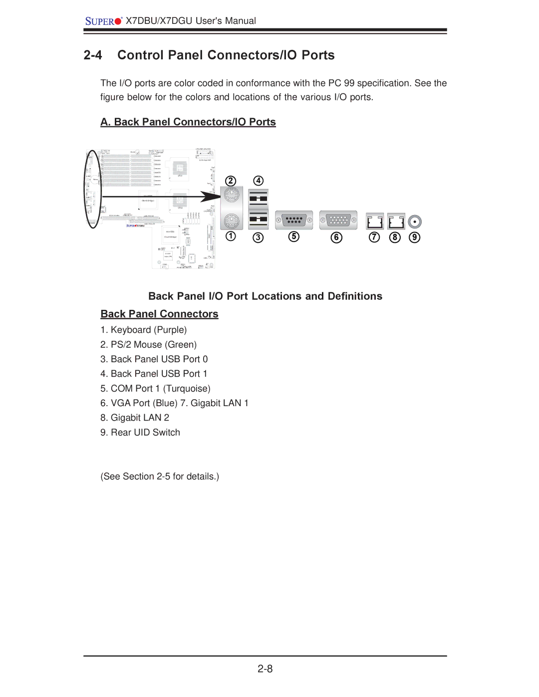
2-4 Control Panel Connectors/IO Ports
The I/O ports are color coded in conformance with the PC 99 specification. See the figure below for the colors and locations of the various I/O ports.
A. Back Panel Connectors/IO Ports
S | 4kn aB | Fan6 | Fan5 |
/MBK /10SB | 2J9B B1J9 |
| |
| JKM1 |
|
|
Uk3 3 n J8B aB 2
1M | BJ8 |
Ck2![]()
![]() 1J8B
1J8B
JCOM1 naB![]()
![]() 3J7BO
3J7BO
Battery |
| 2 |
AGV | 1kn aB | BJ7 1J7B |
J15 |
|
|
1NA L |
|
|
JLAN1 |
|
|
2NLA |
|
|
JLAN2 |
|
|
IDU |
| LAN |
r |
|
|
2EL 1W aRe |
| CTRL |
S |
|
|
|
| |
|
| 4J1 |
J11 |
|
|
UIO PWR |
|
|
| Buzzer | Fan7 | 7J1 |
|
|
|
|
|
| PWR SMB |
|
|
|
|
| ||
| SP1 | CPU Fan1 |
|
|
|
|
|
|
|
| DIMM4B |
|
|
|
|
|
|
|
| DIMM4A |
|
|
|
|
|
|
|
| DIMM3B |
|
|
|
|
|
|
|
| DIMM3A |
|
|
|
|
|
|
|
| DIMM2B |
|
|
|
|
|
|
|
| DIMM2A |
|
| CPU1 |
|
| |
|
| DIMM1B |
|
|
|
|
|
|
|
| DIMM1A |
|
|
|
|
|
|
|
| Intel 5000 |
|
|
|
|
|
|
|
| (North Bridge) |
|
|
|
|
|
|
|
|
|
|
| CPU2 |
|
| |
I2C2 I2C1 | J9 |
|
|
| 0 | |||
J28 | J27 |
|
|
| ||||
SXB2: |
|
|
|
|
|
| ||
|
|
| J5 |
|
| ATA S |
|
|
|
| SXB1: |
|
|
|
|
| |
|
|
|
|
|
|
|
| |
| X7DBU |
|
|
|
|
|
| |
|
|
|
|
|
| SGPIO1 |
| |
|
|
| Intel ESB2 |
| J29 |
|
| |
|
|
|
| J30 |
|
| ||
|
|
|
|
|
| SGPIO2 |
| |
|
|
| (South Bridge) |
|
|
|
| |
|
|
|
|
|
| Memory | SIO B |
|
|
|
| JPG1 | J7 | JBT1 |
|
| |
|
|
| JWOR1 |
|
|
|
| |
|
|
| ES1000 |
|
| Video |
|
|
|
|
| Video CTRL |
|
| JWD |
| I/OS |
|
|
|
|
|
| JK1 |
| |
|
|
| COM2 |
|
| JWOL1 |
|
|
|
|
|
|
| JPL1 | JPL2 | USB4 | |
|
|
|
|
|
|
|
| |
|
|
|
|
|
| |||||||||
| 2WJP |
|
|
|
|
|
| 3WJP |
|
|
|
|
| |
|
|
|
|
|
|
|
|
|
|
|
| |||
| 1W JP |
|
|
|
|
|
|
|
|
|
|
|
|
|
|
|
|
|
|
|
| ||||||||
|
|
|
|
|
|
|
|
|
|
| Fan1 | |||
|
|
|
|
|
|
|
|
|
|
|
|
|
|
|
|
|
|
|
|
|
|
|
|
| LTR CFP |
| JF1 |
|
|
|
|
|
|
|
|
|
|
|
|
|
|
|
| |
|
|
|
|
|
|
| Fan2 |
|
|
|
|
| ||
|
|
|
|
|
|
|
|
|
|
|
|
|
|
|
|
|
|
|
|
|
|
| LE1 |
|
|
| |||
|
|
|
|
|
|
|
|
|
| Fan3 |
|
| ||
|
|
|
|
|
| Fan8 |
|
|
|
|
| |||
3TA | 4AT |
|
| CPU FAN2 |
|
|
|
|
| |||||
5ATA |
|
|
|
|
| |||||||||
|
|
|
|
|
|
|
|
|
|
| 1#E ID |
| ||
|
|
|
|
|
|
|
|
|
|
|
| |||
|
|
|
|
|
|
| OSIM S |
|
|
|
|
| ||
|
|
|
|
|
|
|
|
|
|
| ypp loF |
| ||
|
|
|
|
|
|
| J18 |
| J22 |
| ||||
|
|
|
| SMB |
|
|
| |||||||
|
|
|
|
| JL1 |
|
|
|
|
| ||||
|
|
|
|
|
|
|
|
|
| |||||
|
| USB2/3 |
|
|
|
|
| Fan4 | ||||||
24
1 | 3 | 5 | 6 | 7 | 8 | 9 |
Back Panel I/O Port Locations and Definitions
Back Panel Connectors
1.Keyboard (Purple)
2.PS/2 Mouse (Green)
3.Back Panel USB Port 0
4.Back Panel USB Port 1
5.COM Port 1 (Turquoise)
6.VGA Port (Blue) 7. Gigabit LAN 1
8.Gigabit LAN 2
9.Rear UID Switch
(See Section