![]()
![]()
![]()
![]() X7DBU/X7DGU User's Manual
X7DBU/X7DGU User's Manual
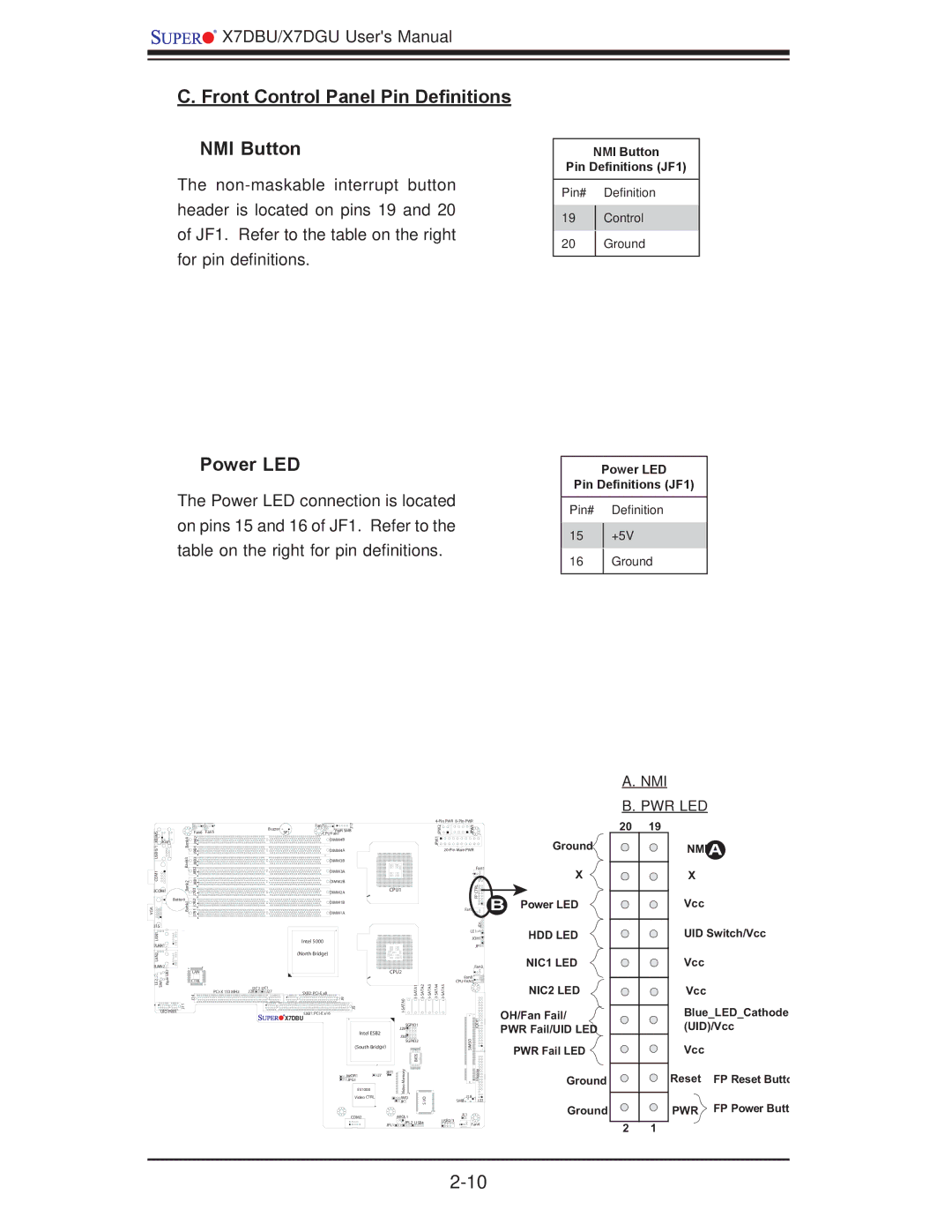
C. Front Control Panel Pin Definitions
NMI Button
The
Power LED
The Power LED connection is located on pins 15 and 16 of JF1. Refer to the table on the right for pin definitions.
NMI Button
Pin Definitions (JF1)
Pin# Definition
19Control
20Ground
Power LED
Pin Definitions (JF1)
Pin# Definition
15+5V
16Ground
A.NMI
B.PWR LED
KB/MS0/1 USBCOM1 | Bank4 Bank3 | Fan6 | Fan5 |
J9B1J9B2 J8B2J8B3J8B1 |
| ||
JKM1 |
|
|
|
JCOM1 | Bank2 | J7B3 |
|
| Battery | J7B2 | |
VGA | Bank1 | ||
J7B1 | |||
J15 |
|
| |
LAN1 |
|
| |
JLAN1 |
|
| |
LAN2 |
|
| |
JLAN2 | UID |
| |
| LAN | ||
LE2 SW1 | Rear | CTRL | |
|
| ||
|
| J14 | |
| J11 |
| |
UIO PWR |
| ||
| Buzzer | Fan7 | J17 |
|
|
|
|
|
| PWR SMB |
|
|
|
|
| ||
| SP1 | CPU Fan1 |
|
|
|
|
|
|
|
| DIMM4B |
|
|
|
|
|
|
|
| DIMM4A |
|
|
|
|
|
|
|
| DIMM3B |
|
|
|
|
|
|
|
| DIMM3A |
|
|
|
|
|
|
|
| DIMM2B |
|
|
|
|
|
|
|
| DIMM2A |
|
| CPU1 |
|
| |
|
|
|
|
|
|
|
| |
|
| DIMM1B |
|
|
|
|
|
|
|
| DIMM1A |
|
|
|
|
|
|
|
| Intel 5000 |
|
|
|
|
|
|
|
| (North Bridge) |
|
|
|
|
|
|
|
|
|
|
| CPU2 |
|
| |
I2C2 | I2C1 | J9 | J5 |
|
| SATA0 | ||
J28 | J27 | SXB2: |
|
|
|
|
|
|
|
| SXB1: |
|
|
|
|
| |
|
|
|
|
|
|
|
| |
| X7DBU |
|
|
|
|
|
| |
|
|
|
|
|
| SGPIO1 |
| |
|
|
| Intel ESB2 |
| J29 |
|
| |
|
|
|
| J30 |
|
| ||
|
|
|
|
|
|
|
| |
|
|
|
|
|
| SGPIO2 |
| |
|
|
| (South Bridge) |
|
|
|
| |
|
|
|
|
|
| Memory | BIOS |
|
|
|
| JWOR1 | J7 | JBT1 |
|
| |
|
|
|
|
|
|
| ||
|
|
| JPG1 |
|
| Video |
|
|
|
|
| ES1000 |
|
|
|
| |
|
|
| Video CTRL |
|
| JWD |
| I/O |
|
|
|
|
|
| JK1 |
| |
|
|
|
|
|
|
|
| S |
|
|
| COM2 |
|
| JWOL1 |
|
|
|
|
|
|
| JPL1 | JPL2 | USB4 | |
|
|
|
|
|
|
|
| |
| ||
| JPW2 | JPW3 |
| JPW1 |
|
|
| |
|
| Fan1 |
|
| JF1 |
|
| CTRLFP |
|
| Fan2 |
|
| JD1 |
|
| LE1 |
|
| JOH1 |
|
| JP1 |
|
| Fan3 |
|
| Fan8 |
CPU FAN2 | ||
|
| IDE#1 |
|
| SIMSO |
|
| Floppy |
| J18 |
SMB | J22 |
JL1
USB2/3
Fan4
Ground
X
BPower LED
HDD LED
NIC1 LED
NIC2 LED
OH/Fan Fail/ PWR Fail/UID LED
PWR Fail LED
Ground
Ground
20 | 19 |
| NMIA |
| X |
| Vcc |
UID Switch/Vcc
Vcc
Vcc
Blue_LED_Cathode (UID)/Vcc
Vcc
Reset | FP Reset Butto |
PWR | FP Power Butt |
2 1