Chapter 2: Installation
2-7 Onboard Indicators
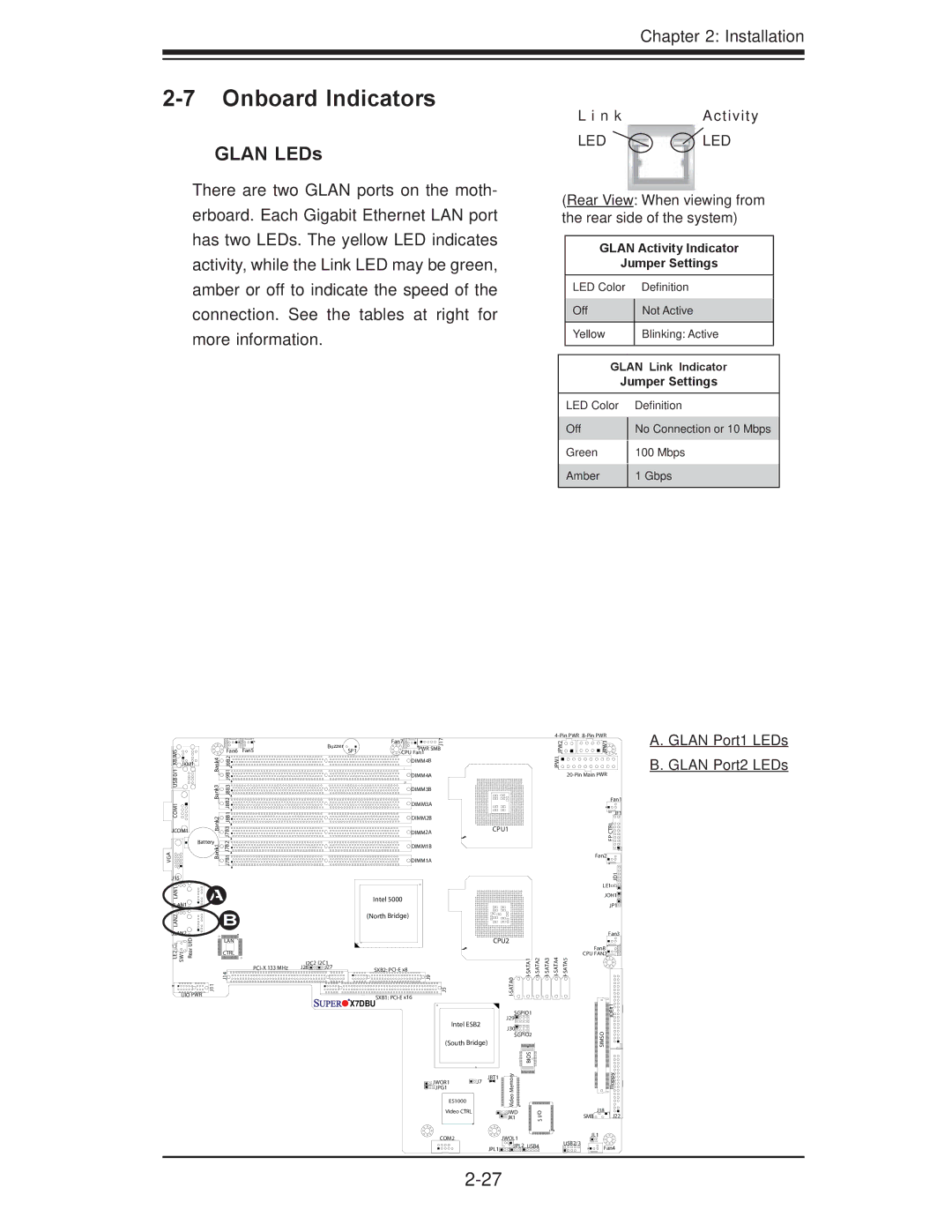
GLAN LEDs
There are two GLAN ports on the moth- erboard. Each Gigabit Ethernet LAN port has two LEDs. The yellow LED indicates activity, while the Link LED may be green, amber or off to indicate the speed of the connection. See the tables at right for more information.
L i n k | Activity |
LED | LED |
(Rear View: When viewing from the rear side of the system)
GLAN Activity Indicator
Jumper Settings
LED Color |
| Definition |
Off |
| Not Active |
| ||
|
|
|
Yellow |
| Blinking: Active |
|
|
|
GLAN Link Indicator
Jumper Settings
LED Color
Off
Green
Amber
Definition
No Connection or 10 Mbps
100Mbps
1Gbps
|
|
|
|
|
|
|
| Fan7 | 17 |
|
|
|
|
| 2PW J |
| 3PW J |
|
|
|
|
|
| Buzzer |
|
| J |
|
|
|
|
|
| ||
KB/MS0/1 USBCOM1 |
|
| Fan6 | Fan5 |
|
| PWR SMB |
|
|
|
|
|
| ||||
|
|
| SP1 |
|
|
|
|
|
|
| |||||||
| Bank4 Bank3 |
|
| CPU Fan1 |
|
|
|
|
|
|
| ||||||
| J9B1J9B2 J8B2J8B3J8B1 |
|
|
|
| DIMM4B |
|
|
|
|
|
| 1JPW |
|
| ||
JKM1 |
|
|
|
|
|
|
|
|
|
|
|
|
|
|
|
| |
|
|
|
|
|
|
|
| DIMM4A |
|
|
|
|
|
|
| ||
|
|
|
|
|
|
|
| DIMM3B |
|
|
|
|
|
|
|
|
|
|
|
|
|
|
|
|
| DIMM3A |
|
|
|
|
|
|
|
| Fan1 |
|
|
|
|
|
|
|
|
|
|
|
|
|
|
|
|
| |
|
| Bank2 |
|
|
|
|
| DIMM2B |
|
|
|
|
|
|
|
| JF1 |
|
| J7B3 |
|
|
|
|
|
|
|
|
|
|
|
| RLCTP | ||
JCOM1 |
|
|
|
| DIMM2A |
| CPU1 |
|
|
|
|
| |||||
| Battery | J7B2 |
|
|
|
|
|
|
|
|
|
|
|
|
| F | |
VGA |
| Bank1 |
|
|
|
| DIMM1B |
|
|
|
|
|
|
|
| ||
| J7B1 |
|
|
|
|
|
|
|
|
|
|
|
|
| |||
|
|
|
|
| DIMM1A |
|
|
|
|
|
|
|
| Fan2 | |||
|
|
|
|
|
|
|
|
|
|
|
|
|
|
|
|
| |
J15 |
|
|
|
|
|
|
|
|
|
|
|
|
|
|
|
| 1DJ |
LAN1 |
| A |
|
|
|
|
|
|
|
|
|
|
|
|
| LE1 | |
|
|
|
| Intel 5000 |
|
|
|
|
|
|
|
| JOH1 | ||||
JLAN1 |
|
|
|
|
|
|
|
|
|
|
|
| JP1 | ||||
LAN2 |
|
| B |
|
|
| (North Bridge) |
|
|
|
|
|
|
|
|
| |
|
|
|
|
|
|
|
|
|
|
|
|
|
|
|
| ||
JLAN2 | UID |
|
|
|
|
|
|
|
|
|
|
|
|
|
|
| Fan3 |
|
| LAN |
|
|
|
|
|
| CPU2 |
|
|
|
|
|
| ||
|
|
|
|
|
|
|
|
|
|
|
|
|
|
| |||
LE2 SW1 | Rear |
| J14 |
|
|
|
| 9J |
|
| 0 | Fan8 | |||||
|
|
| CTRL |
|
|
|
|
|
|
|
|
|
|
|
| CPU FAN2 | |
|
|
|
| I2C2 | I2C1 |
|
|
|
|
|
|
|
|
|
|
| |
|
|
|
| J28 | J27 | SXB2: |
|
|
|
|
|
|
|
|
| ||
UIO PWR | J11 |
|
|
|
|
| SXB1: | 5J |
| ATA |
|
|
|
|
|
| |
|
|
|
|
|
| X7DBU |
|
|
|
|
|
|
|
|
| ||
|
|
|
|
|
|
|
|
|
|
|
|
|
|
| 1# | ||
|
|
|
|
|
|
|
|
|
|
| SGPIO1 |
|
|
|
| E | |
|
|
|
|
|
|
|
|
|
|
|
|
|
|
| ID | ||
|
|
|
|
|
|
|
|
|
|
| J29 |
|
|
|
|
| |
|
|
|
|
|
|
|
|
| Intel ESB2 |
|
|
|
|
|
| ||
|
|
|
|
|
|
|
|
| J30 |
|
|
|
|
|
| ||
|
|
|
|
|
|
|
|
|
|
|
|
|
|
|
| O | |
|
|
|
|
|
|
|
|
|
|
| SGPIO2 |
|
|
|
| ||
|
|
|
|
|
|
|
|
| (South Bridge) |
|
|
|
|
|
| SIM | |
|
|
|
|
|
|
|
|
|
|
|
|
|
|
|
|
| S |
|
|
|
|
|
|
|
|
|
|
| yromeM | SIO B |
|
|
|
| ypploF |
|
|
|
|
|
|
|
|
| JWOR1 | JBT1 |
|
|
|
|
| ||
|
|
|
|
|
|
|
|
| J7 |
|
|
|
|
|
|
| |
|
|
|
|
|
|
|
|
| JPG1 |
|
|
|
|
|
|
|
|
|
|
|
|
|
|
|
|
| ES1000 |
| oe |
|
|
|
|
|
|
|
|
|
|
|
|
|
|
|
| Vid |
|
|
|
|
|
| |
|
|
|
|
|
|
|
|
|
|
|
|
|
|
|
| J18 | |
|
|
|
|
|
|
|
|
| Video CTRL |
| JWD |
| I/O |
|
|
| |
|
|
|
|
|
|
|
|
|
|
| JK1 |
|
|
| SMB | J22 | |
|
|
|
|
|
|
|
|
|
|
|
|
| S |
|
|
|
|
|
|
|
|
|
|
|
|
| COM2 | JWOL1 |
|
|
|
| JL1 | ||
|
|
|
|
|
|
|
|
|
|
|
|
| USB2/3 |
| |||
|
|
|
|
|
|
|
|
|
| JPL1 | JPL2 | USB4 |
|
| Fan4 | ||
|
|
|
|
|
|
|
|
|
|
|
|
| |||||
|
|
|
|
|
|
|
|
|
|
|
|
|
|
|
| ||
|
|
|
|
|
|
|
|
|
|
|
|
|
|
|
| ||
A. GLAN Port1 LEDs B. GLAN Port2 LEDs