![]()
![]()
![]()
![]() X7DBU/X7DGU User's Manual
X7DBU/X7DGU User's Manual
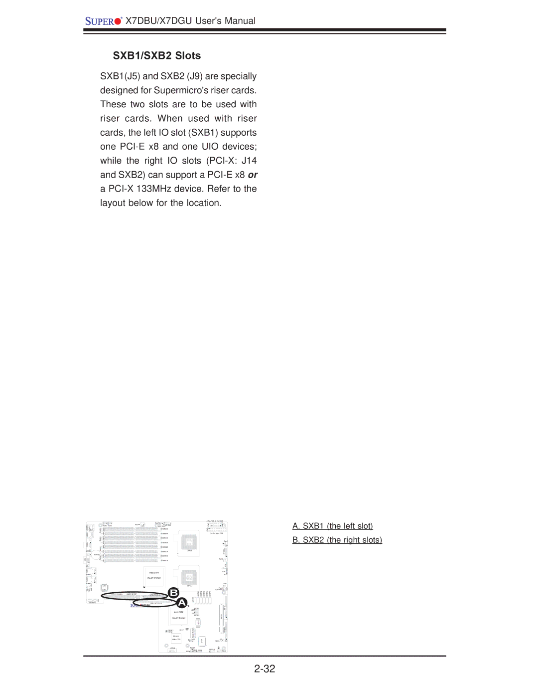
SXB1/SXB2 Slots
SXB1(J5) and SXB2 (J9) are specially designed for Supermicro's riser cards. These two slots are to be used with riser cards. When used with riser cards, the left IO slot (SXB1) supports one
a
KB/MS0/1 COM1USB | Bank4 Bank3 | Fan6 | Fan5 |
J9B1J9B2 J8B2J8B1J8B3 |
| ||
JKM1 |
|
|
|
JCOM1 | Bank2 | J7B3 |
|
| Battery | J7B2 | |
VGA | Bank1 | ||
J7B1 | |||
J15 |
|
| |
LAN1 |
|
| |
JLAN1 |
| ||
LAN2 |
|
| |
JLAN2 | UID |
| |
| LAN | ||
LE2 SW1 | Rear | CTRL | |
|
| ||
|
| J14 | |
| J11 |
| |
UIO PWR |
| ||
| Buzzer | Fan7 | J17 |
|
|
|
|
|
|
| PWR SMB |
|
|
|
|
|
| ||
| SP1 | CPU Fan1 |
|
|
|
|
|
|
|
|
| DIMM4B |
|
|
|
|
|
|
|
|
| DIMM4A |
|
|
|
|
|
|
|
|
| DIMM3B |
|
|
|
|
|
|
|
|
| DIMM3A |
|
|
|
|
|
|
|
|
| DIMM2B |
|
|
|
|
|
|
|
|
| DIMM2A |
|
|
| CPU1 |
|
| |
|
| DIMM1B |
|
|
|
|
|
|
|
|
| DIMM1A |
|
|
|
|
|
|
|
|
| Intel 5000 |
|
|
|
|
|
|
|
|
| (North Bridge) |
|
|
|
|
|
|
|
|
|
| B |
|
| CPU2 |
|
| |
I2C2 | I2C1 | J9 |
|
|
| SATA0 | |||
J5 |
|
|
| ||||||
J28 | J27 | SXB2: |
|
|
|
|
|
|
|
|
| SXB1: |
| A |
|
|
| ||
|
|
|
|
|
|
| |||
| X7DBU |
|
| SGPIO1 |
| ||||
|
|
| Intel ESB2 |
| J29 |
|
| ||
|
|
|
| J30 |
|
| |||
|
|
|
|
|
|
|
|
| |
|
|
|
|
|
|
| SGPIO2 |
| |
|
|
| (South Bridge) |
|
|
|
| ||
|
|
|
|
|
|
|
| BIOS |
|
|
|
|
|
| JBT1 | ryo |
|
| |
|
|
| JWOR1 |
| J7 |
| m |
|
|
|
|
| JPG1 |
|
|
| e |
|
|
|
|
| ES1000 |
|
| Meoid |
|
| |
|
|
|
|
|
|
| V |
|
|
|
|
| Video CTRL |
|
| JWD |
| I/OS | |
|
|
|
|
|
|
| JK1 |
| |
|
|
| COM2 |
|
|
| JWOL1 |
|
|
|
|
|
|
| JPL1 | JPL2 | USB4 | ||
| ||
JPW2 | JPW3 |
|
JPW1 |
|
|
|
| |
|
| Fan1 |
|
| JF1 |
|
| CTRLFP |
| Fan2 |
|
|
| JD1 |
| LE1 | |
| JOH1 | |
|
| JP1 |
|
| Fan3 |
| Fan8 |
|
CPU FAN2 |
| |
| ||
|
| IDE#1 |
| SIMSO |
|
|
| Floppy |
| J18 | J22 |
| SMB | |
| JL1 |
|
| USB2/3 |
|
| Fan4 | |
A. SXB1 (the left slot) B. SXB2 (the right slots)