ASSEMBLY INSTRUCTIONS | ENGLISH | ||
4. Assemble the two OUTER hitch braces to the hitch tube | |||
|
| ||
|
| using a 1/4" x | |
TOOLS REQUIRED FOR ASSEMBLY | nut (C). DO NOT TIGHTEN YET. Do not assemble the | ||
inner hitch braces at this time. See figure 2. | |||
(1) | Pliers |
| |
(2) | 7/16" Wrenches | HITCH | |
(2) | 1/2" Wrenches | ||
TUBE | |||
(2) | 9/16" Wrenches | ||
| |||
REMOVAL OF PARTS FROM CARTON
Remove all parts and hardware packages from the carton. Lay out all parts and hardware and identify using the illustrations on page 2.
|
| (B) 1/4" x | (C) 1/4" NYLOCK | ||
1. | Turn the spreader upside down as shown in figure 1. | HEX BOLT |
| HEX NUT | |
HITCH BRACE |
| ||||
2. | Remove the lock nut from the middle bolt in the crossover | HITCH BRACE | |||
| tube and shaft support plate. Leave the bolt in place. |
| OUTER |
| |
|
|
| OUTER | ||
|
|
|
| ||
| See figure 1. |
|
|
|
|
3. | Assemble the hitch tube onto the middle bolt and | FIGURE 2 |
|
|
|
| secure it with the same lock nut you removed. DO NOT |
|
|
|
|
TIGHTEN YET. See figure 1.
IMPORTANT: The hitch tube must attach to the side of the crossover tube opposite the shaft support plate.
| SHAFT |
| SUPPORT |
MIDDLE BOLT | PLATE CROSSOVER |
TUBE | |
HITCH |
|
TUBE |
|
| MIDDLE |
| LOCK NUT |
FIGURE 1
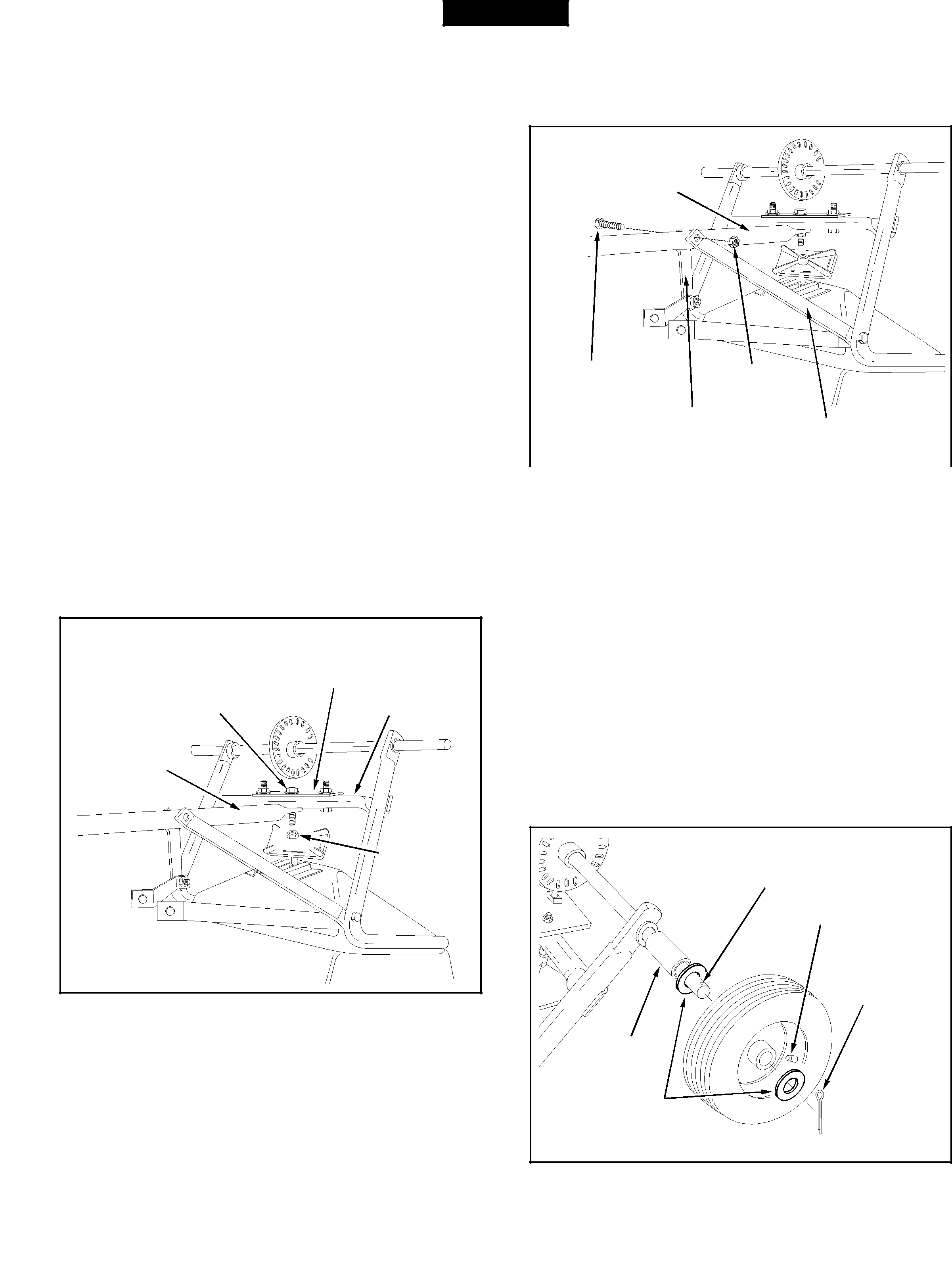
5.Assemble a spacer (I), a 3/4" flat washer (G), a wheel (air valve facing out) and another 3/4" flat washer (G) onto the end of the axle that has only the small hole. See figure 3.
6.Install a 1/8" x
SMALL HOLE
AIR VALVE
(E) 1/8" x
COTTER PIN
(I) SPACER
(G) 3/4" FLAT
WASHER
FIGURE 3
4