ENGLISH
14.Assemble the two INNER hitch braces to the flow control mounting tube using a 1/4" x
15.TIGHTEN all nuts and bolts assembled up to this point.
Do not collapse the tubes when tightening.
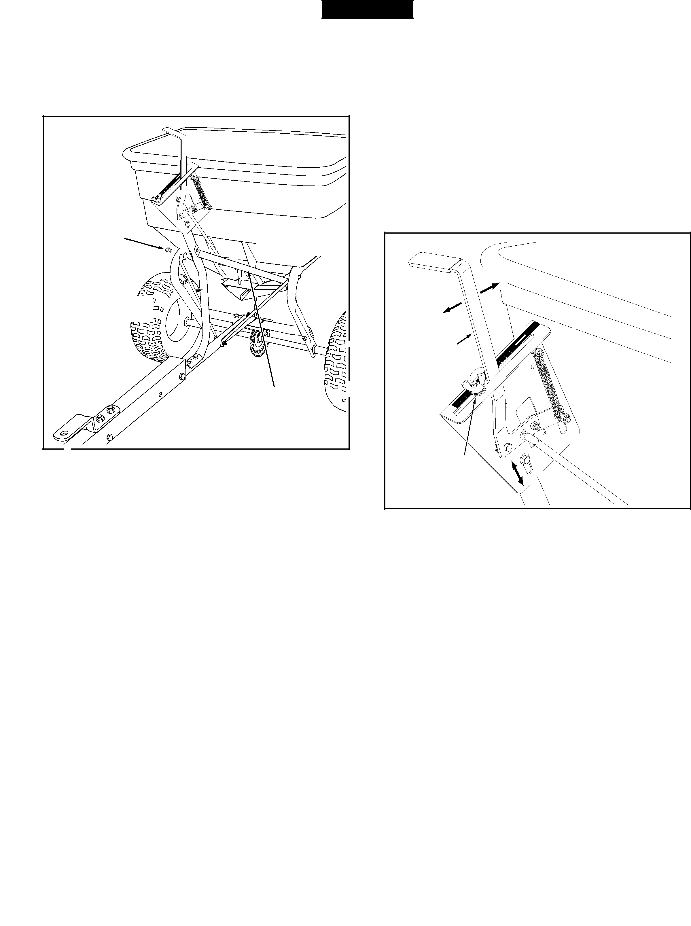
16. Calibrate the flow control setting. (See figure 9). |
a. Push flow control arm to "OFF" position. |
b. Slide flow control mounting bracket along tube until |
closure plate in bottom of hopper just closes. |
c. Snug the 1/4" nylock hex nuts just enough to hold |
flow control mounting bracket in place. |
d. Set adjustable stop at "5". Pull flow control arm |
against stop. Verify that closure plate has opened |
about half way. |
e. If closure plate does not open half way, adjust |
position of flow control mounting bracket until |
OFF
ON
1 2 3  4 5
4 5  6 7
6 7  8
8  9
9  10
10 
(C) 1/4" NYLOCK
HEX NUT
HITCH BRACE 


 (INNER)


FLOW CONTROL
MOUNTING TUBE


(B)1/4" x
 HEX BOLT
closure plate will open about half way at "5" and |
will still close when arm is locked in "OFF" position. |
Tighten the 5/16" nylock hex nuts. |
| OFF |
ON |
|
| OFF |
FLOW | ON |
0 | |
1 | |
CONTROL |
|
ARM | 5 |
6 | |
7 |
HITCH BRACE 

 (INNER)

FIGURE 8
8 |
9 |
10 |
ADJUSTABLE
STOP
(SETTING "5")
FIGURE 9
6