3 | MOUNTING |
|
|
| ||
|
|
|
|
| ||
1 |
|
| [2] | [1] |
|
|
|
|
|
|
|
| |
[1] |
|
|
|
| 200mm | |
|
|
|
| |||
|
|
|
|
| 25mm |
|
|
|
| [2] |
| (1") |
|
|
|
|
| W | 44mm | |
|
|
|
|
| ||
|
|
|
|
|
| |
|
|
|
|
|
| 15mm |
|
|
|
| [1] |
| (1/2") |
[3] |
|
|
|
|
| |
W (mm) | W (inch) |
|
|
| ||
| x 1 | 110 |
|
|
| |
| x 2 | 245 |
|
|
| |
| x 3 | 380 | 15" |
|
| 295mm |
| x 4 | 515 |
|
| ||
|
|
| ||||
| x 5 | 650 |
|
| ||
|
|
|
| |||
| x 6 | 785 |
|
|
| |
| x 7 | 920 |
|
|
| |
| x 8 | 1055 |
|
|
| |
| x 9 | 1190 | 25mm | 25mm |
| |
|
|
|
| (1") | (1") |
|
|
|
|
| W |
| 44mm |
|
|
|
|
|
| |
|
|
|
|
|
| 15mm |
|
|
|
|
|
| (1/2") |
2
[4]
34
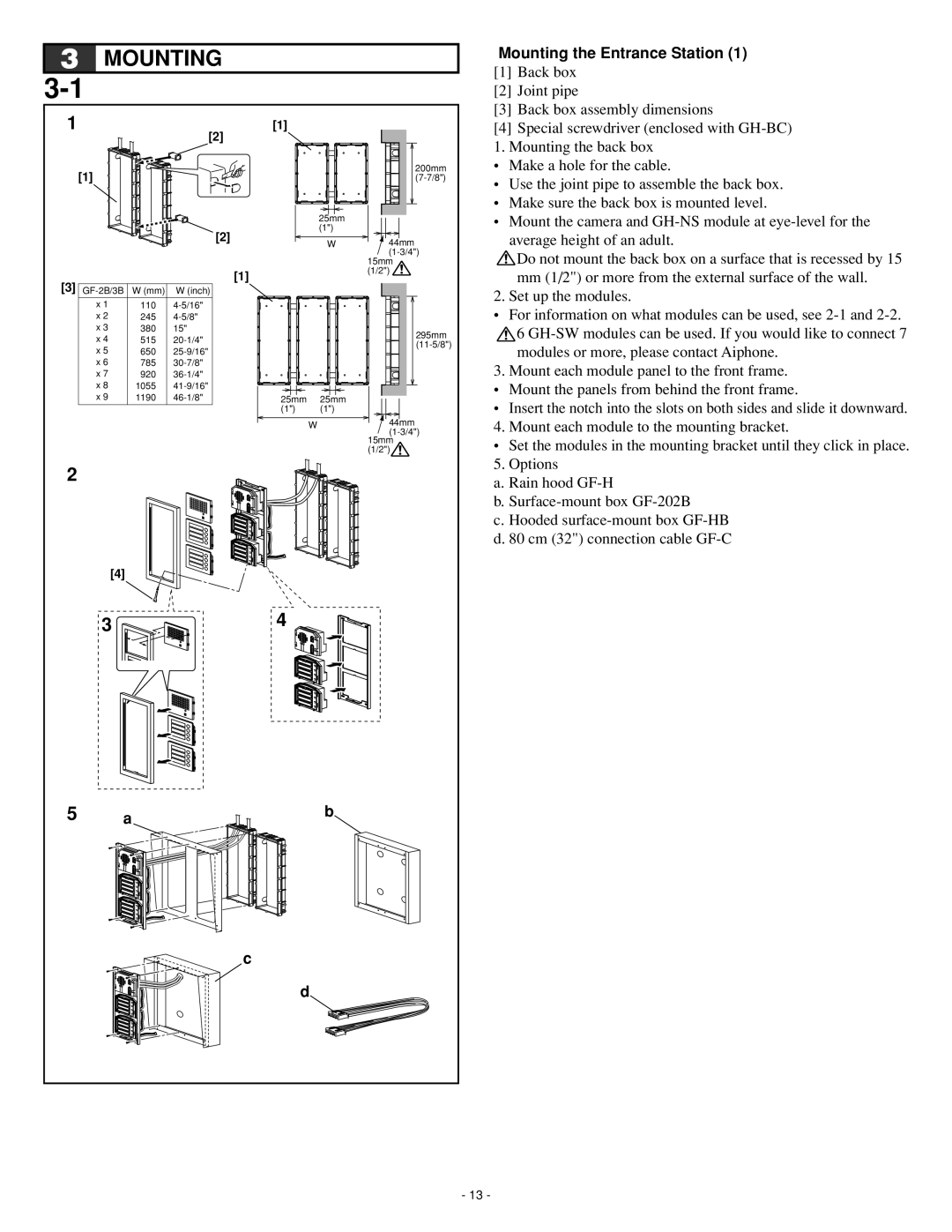
Mounting the Entrance Station (1)
[1]Back box
[2]Joint pipe
[3]Back box assembly dimensions
[4]Special screwdriver (enclosed with
• Make a hole for the cable.
• Use the joint pipe to assemble the back box.
• Make sure the back box is mounted level.
• Mount the camera and
![]() Do not mount the back box on a surface that is recessed by 15 mm (1/2") or more from the external surface of the wall.
Do not mount the back box on a surface that is recessed by 15 mm (1/2") or more from the external surface of the wall.
2. Set up the modules.
•For information on what modules can be used, see
![]() 6
6
3. Mount each module panel to the front frame.
•Mount the panels from behind the front frame.
•Insert the notch into the slots on both sides and slide it downward.
4. Mount each module to the mounting bracket.
•Set the modules in the mounting bracket until they click in place.
5. Options
a. Rain hood
b.
c. Hooded
5 | a | b |
c
d
- 13 -
