1 | 2 | [1] |
[2]
3
45
|
| 1 |
| 2 |
|
| 4 |
|
|
| 3 |
|
| 5 |
|
| |
7 |
|
|
|
| 6 |
| 8 |
|
|
| |
|
|
|
| 9 |
|
| 0 |
|
|
|
|
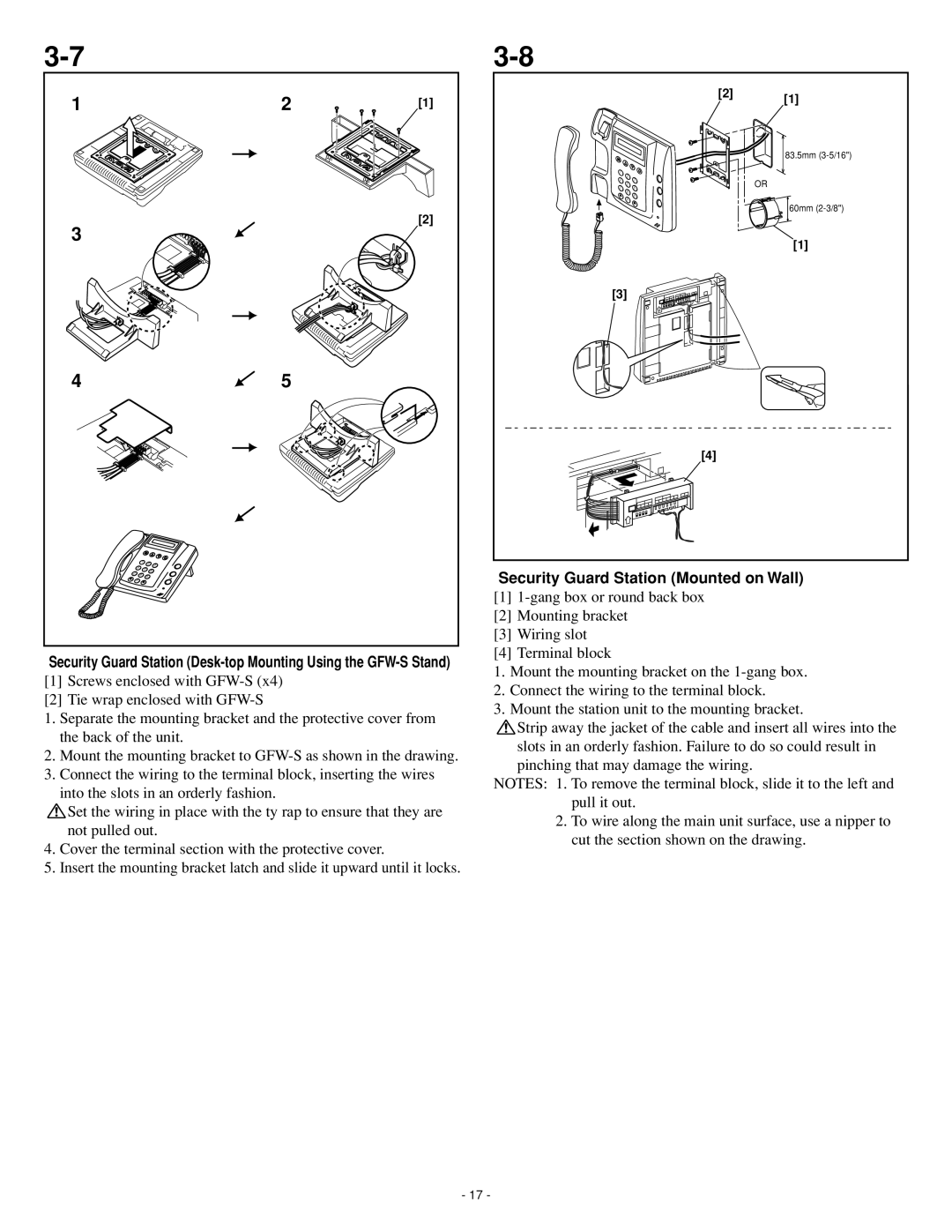
Security Guard Station
[1]Screws enclosed with
[2]Tie wrap enclosed with
1. Separate the mounting bracket and the protective cover from the back of the unit.
2. Mount the mounting bracket to
3. Connect the wiring to the terminal block, inserting the wires into the slots in an orderly fashion.
![]() Set the wiring in place with the ty rap to ensure that they are not pulled out.
Set the wiring in place with the ty rap to ensure that they are not pulled out.
4. Cover the terminal section with the protective cover.
5. Insert the mounting bracket latch and slide it upward until it locks.
[2] [1]
83.5mm
1 | A2 |
|
| |
|
|
| ||
G4 | BC | D3 | OR | |
KL | ||||
7 | M6 | |||
HI | J5 | EF |
| |
|
|
| ||
QR | T8 | NO |
| |
| UV | 9 |
| |
|
|
| ||
| 0 | XY |
| |
|
|
|
60mm
[1]
[3]
[4]
Security Guard Station (Mounted on Wall)
[1]
[2]Mounting bracket
[3]Wiring slot
[4]Terminal block
1.Mount the mounting bracket on the
2.Connect the wiring to the terminal block.
3.Mount the station unit to the mounting bracket.
![]() Strip away the jacket of the cable and insert all wires into the
Strip away the jacket of the cable and insert all wires into the
slots in an orderly fashion. Failure to do so could result in pinching that may damage the wiring.
NOTES: 1. To remove the terminal block, slide it to the left and pull it out.
2. To wire along the main unit surface, use a nipper to cut the section shown on the drawing.
- 17 -
