INSTALLATION & MOUNTING
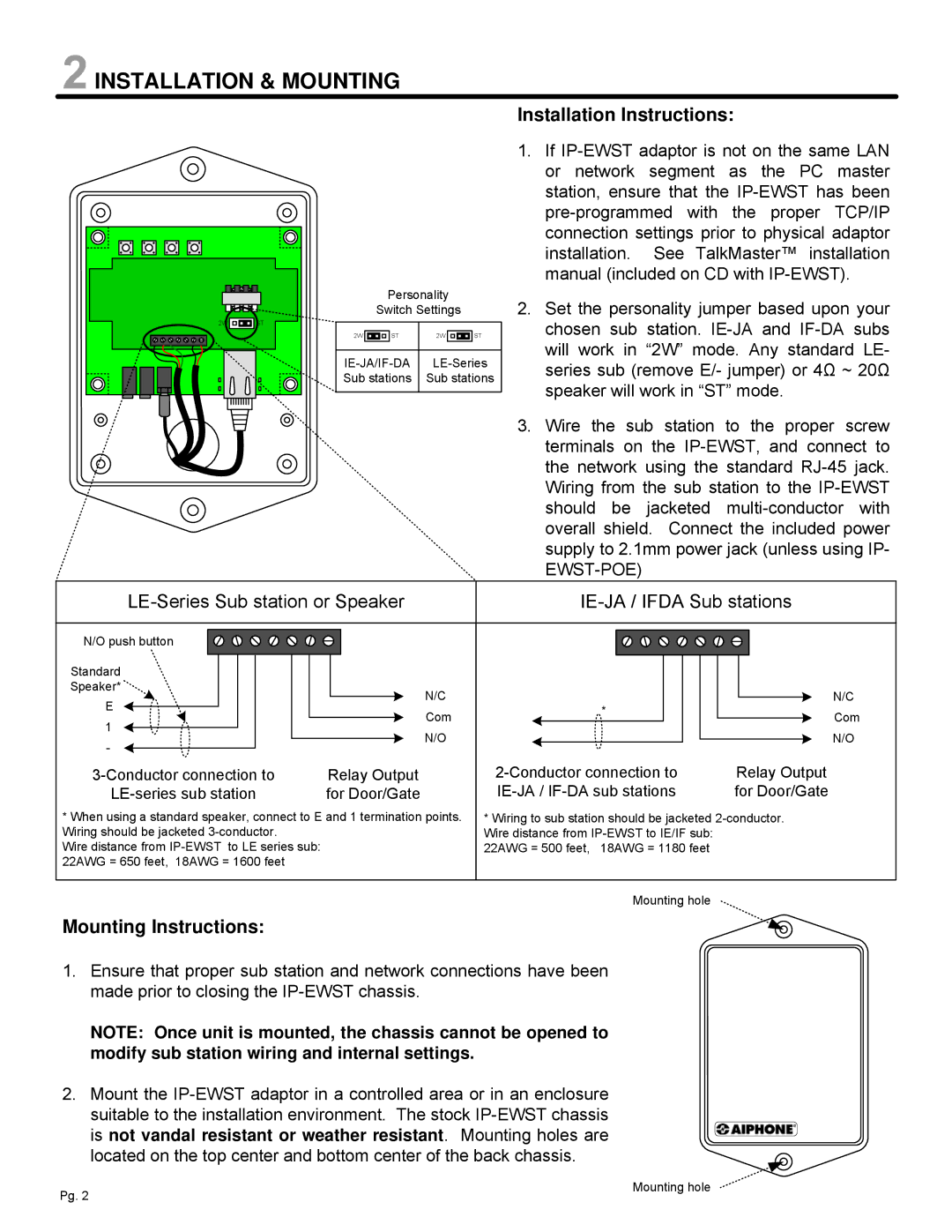
Personality
Switch Settings
2W | | | | ST | 2W | | | | ST |
| | | | | |
| | | | | | | | | |
| | | | | |
IE-JA/IF-DA | LE-Series |
Sub stations | Sub stations |
| | | | | | | | | |
Installation Instructions:
1.If IP-EWST adaptor is not on the same LAN or network segment as the PC master station, ensure that the IP-EWST has been pre-programmed with the proper TCP/IP connection settings prior to physical adaptor installation. See TalkMaster™ installation manual (included on CD with IP-EWST).
2.Set the personality jumper based upon your chosen sub station. IE-JA and IF-DA subs will work in “2W” mode. Any standard LE- series sub (remove E/- jumper) or 4Ω ~ 20Ω speaker will work in “ST” mode.
3.Wire the sub station to the proper screw terminals on the IP-EWST, and connect to the network using the standard RJ-45 jack. Wiring from the sub station to the IP-EWST should be jacketed multi-conductor with overall shield. Connect the included power supply to 2.1mm power jack (unless using IP- EWST-POE)
| LE-Series Sub station or Speaker | | IE-JA / IFDA Sub stations | |
| N/O push button | | | |
| Standard | | | |
| Speaker* | N/C | | N/C |
| E | * |
| Com | Com |
| 1 |
| |
| N/O | | N/O |
| - | |
| | | |
3-Conductor connection to | Relay Output | 2-Conductor connection to | Relay Output |
LE-series sub station | for Door/Gate | IE-JA / IF-DA sub stations | for Door/Gate |
* When using a standard speaker, connect to E and 1 termination points. | * Wiring to sub station should be jacketed 2-conductor. |
Wiring should be jacketed 3-conductor. | | Wire distance from IP-EWST to IE/IF sub: | |
Wire distance from IP-EWST to LE series sub: | | 22AWG = 500 feet, 18AWG = 1180 feet | |
22AWG = 650 feet, 18AWG = 1600 feet | | | |
| | | |
| | Mounting hole | |
Mounting Instructions:
1.Ensure that proper sub station and network connections have been made prior to closing the IP-EWST chassis.
NOTE: Once unit is mounted, the chassis cannot be opened to modify sub station wiring and internal settings.
2.Mount the IP-EWST adaptor in a controlled area or in an enclosure
suitable to the installation environment. The stock IP-EWST chassis is not vandal resistant or weather resistant. Mounting holes are located on the top center and bottom center of the back chassis.