2 Description
2.1Introduction
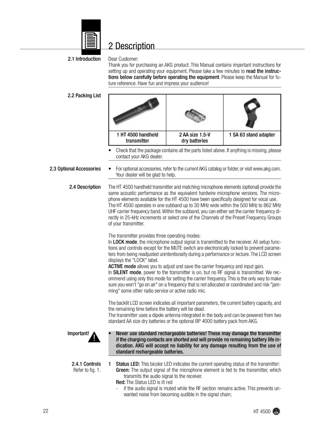
2.2Packing List
Dear Customer:
Thank you for purchasing an AKG product. This Manual contains important instructions for setting up and operating your equipment. Please take a few minutes to read the instruc- tions below carefully before operating the equipment. Please keep the Manual for fu- ture reference. Have fun and impress your audience!
|
|
|
1 HT 4500 handheld | 2 AA size | 1 SA 63 stand adapter |
transmitter | dry batteries |
|
|
|
|
| • | Check that the package contains all the parts listed above. If anything is missing, please |
|
| contact your AKG dealer. |
2.3 Optional Accessories | • | For optional accessories, refer to the current AKG catalog or folder, or visit www.akg.com. |
|
| Your dealer will be glad to help. |
2.4Description The HT 4500 handheld transmitter and matching microphone elements (optional) provide the same acoustic performance as the equivalent hardwire microphone versions. The micro- phone elements available for the HT 4500 have been specifically designed for vocal use.
The HT 4500 operates in one subband up to 30 MHz wide within the 500 MHz to 862 MHz UHF carrier frequency band. Within the subband, you can either set the carrier frequency di- rectly in
|
| The transmitter provides three operating modes: |
|
| In LOCK mode, the microphone output signal is transmitted to the receiver. All setup func- |
|
| tions and controls except for the MUTE switch are electronically locked to prevent parame- |
|
| ters from being readjusted unintentionally during a performance or lecture. The LCD screen |
|
| displays the "LOCK" label. |
|
| ACTIVE mode allows you to adjust and save the carrier frequency and input gain. |
|
| In SILENT mode, power to the transmitter is on, but no RF signal is transmitted. We rec- |
|
| ommend using only this mode for setting the carrier frequency. This is the only way to make |
|
| sure you won't "go on air" on a frequency that is not allocated or coordinated and risk "jam- |
|
| ming" some other radio service or active radio mic. |
|
| The backlit LCD screen indicates all important parameters, the current battery capacity, and |
|
| the remaining time before the battery will be dead. |
|
| The transmitter uses a dipole antenna integrated in the body and can be powered from two |
|
| standard AA size dry batteries or the optional BP 4000 battery pack from AKG. |
▲ |
| |
Important! | ! | • Never use standard rechargeable batteries! These may damage the transmitter |
| if the charging contacts are shorted and will provide no remaining battery life in- | |
|
| dication. AKG will accept no liability for any damage resulting from the use of |
|
| standard rechargeable batteries. |
2.4.1 Controls | 1 Status LED: This bicolor LED indicates the current operating status of the transmitter: | |
Refer to fig. 1. | Green: The output signal of the microphone element is fed to the transmitter, which | |
|
| transmits the audio signal to the receiver. |
|
| Red: The Status LED is lit red |
|
| - if the audio signal is muted while the RF section remains active. This prevents un- |
|
| wanted noise from becoming audible in the signal chain; |
22 |
| HT 4500 |