ASSEMBLY
KNIFE ASSEMBLY
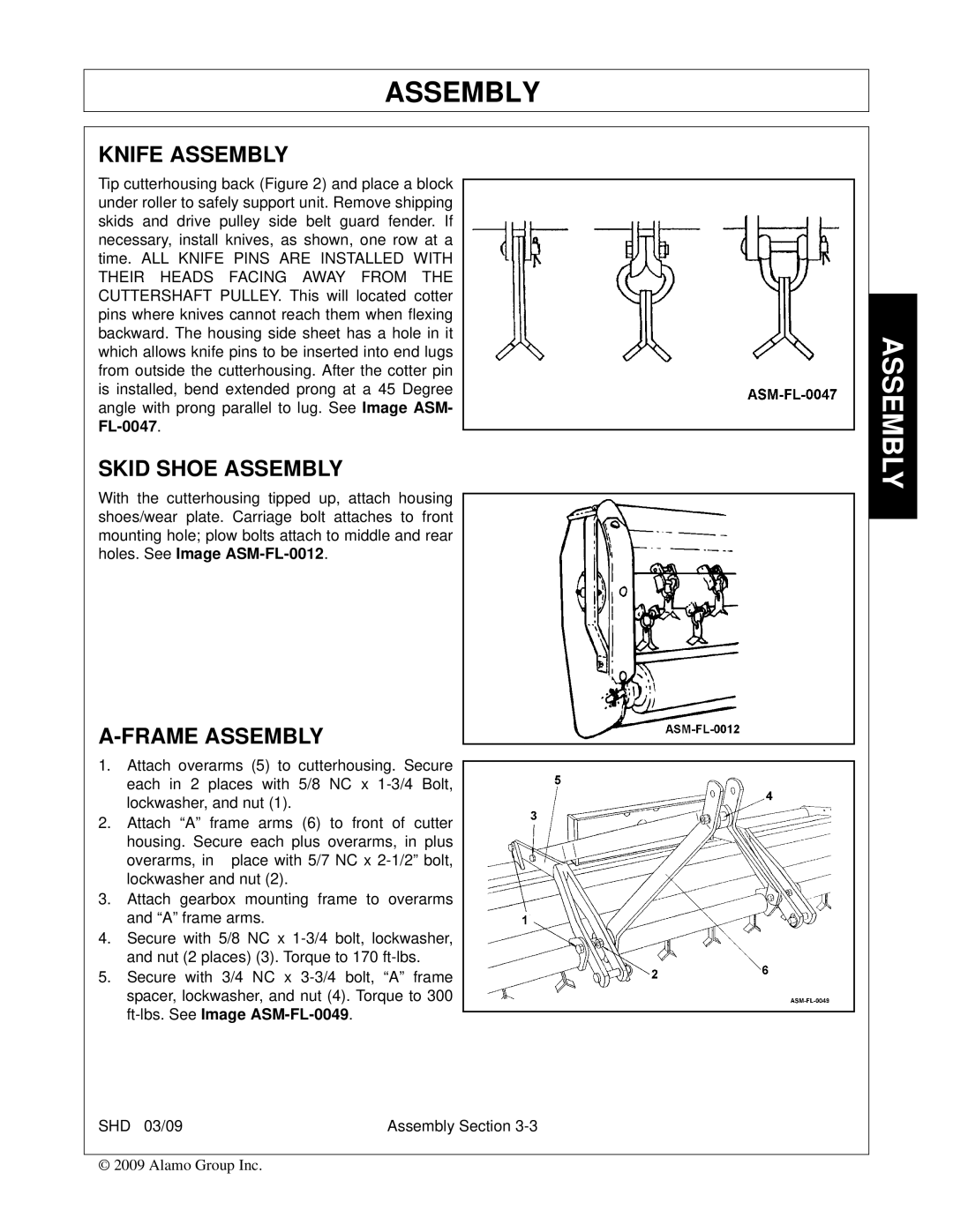
Tip cutterhousing back (Figure 2) and place a block under roller to safely support unit. Remove shipping skids and drive pulley side belt guard fender. If necessary, install knives, as shown, one row at a time. ALL KNIFE PINS ARE INSTALLED WITH THEIR HEADS FACING AWAY FROM THE CUTTERSHAFT PULLEY. This will located cotter pins where knives cannot reach them when flexing backward. The housing side sheet has a hole in it which allows knife pins to be inserted into end lugs from outside the cutterhousing. After the cotter pin is installed, bend extended prong at a 45 Degree angle with prong parallel to lug. See Image ASM-
SKID SHOE ASSEMBLY
With the cutterhousing tipped up, attach housing shoes/wear plate. Carriage bolt attaches to front mounting hole; plow bolts attach to middle and rear holes. See Image
A-FRAME ASSEMBLY
1.Attach overarms (5) to cutterhousing. Secure each in 2 places with 5/8 NC x
2.Attach “A” frame arms (6) to front of cutter housing. Secure each plus overarms, in plus
overarms, in place with 5/7 NC x
3.Attach gearbox mounting frame to overarms and “A” frame arms.
4.Secure with 5/8 NC x
5.Secure with 3/4 NC x
SHD 03/09 | Assembly Section |
© 2009 Alamo Group Inc.