ASSEMBLY
ASSEMBLY
SKID SHOE ASSEMBLY
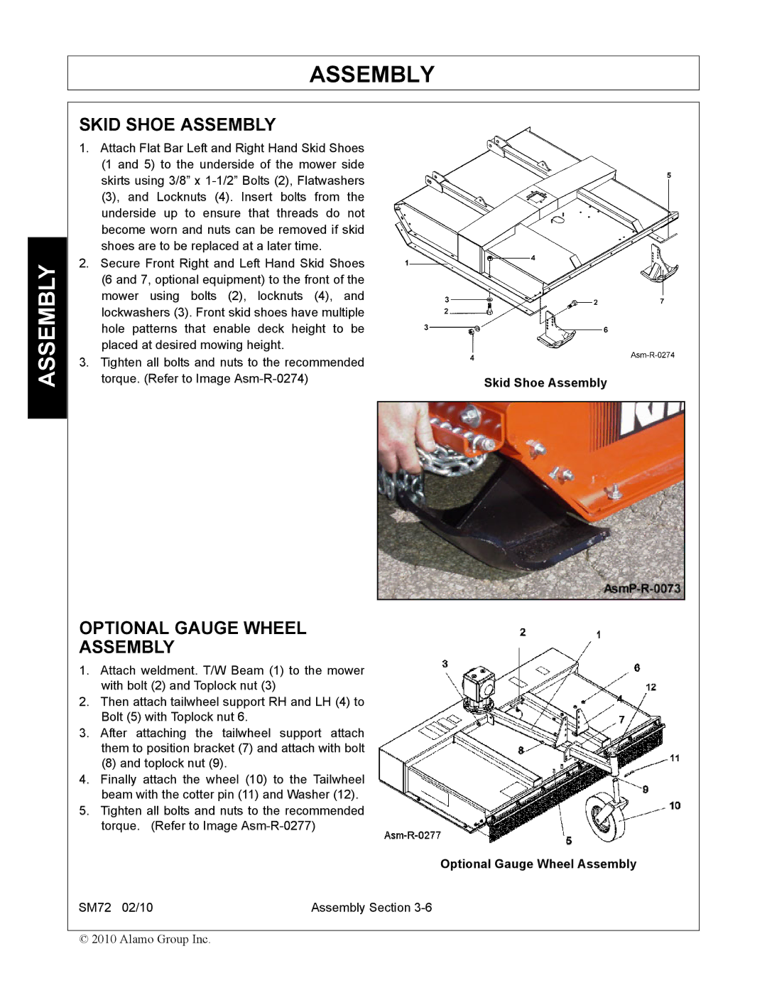
1.Attach Flat Bar Left and Right Hand Skid Shoes (1 and 5) to the underside of the mower side skirts using 3/8” x
2.Secure Front Right and Left Hand Skid Shoes (6 and 7, optional equipment) to the front of the mower using bolts (2), locknuts (4), and lockwashers (3). Front skid shoes have multiple hole patterns that enable deck height to be placed at desired mowing height.
3.Tighten all bolts and nuts to the recommended
torque. (Refer to Image | Skid Shoe Assembly |
|
|
|
|
OPTIONAL GAUGE WHEEL
ASSEMBLY
1.Attach weldment. T/W Beam (1) to the mower with bolt (2) and Toplock nut (3)
2.Then attach tailwheel support RH and LH (4) to Bolt (5) with Toplock nut 6.
3.After attaching the tailwheel support attach them to position bracket (7) and attach with bolt
(8) and toplock nut (9).
4.Finally attach the wheel (10) to the Tailwheel beam with the cotter pin (11) and Washer (12).
5.Tighten all bolts and nuts to the recommended torque. (Refer to Image
Optional Gauge Wheel Assembly
SM72 02/10 | Assembly Section |
© 2010 Alamo Group Inc.
