4
Main power connection
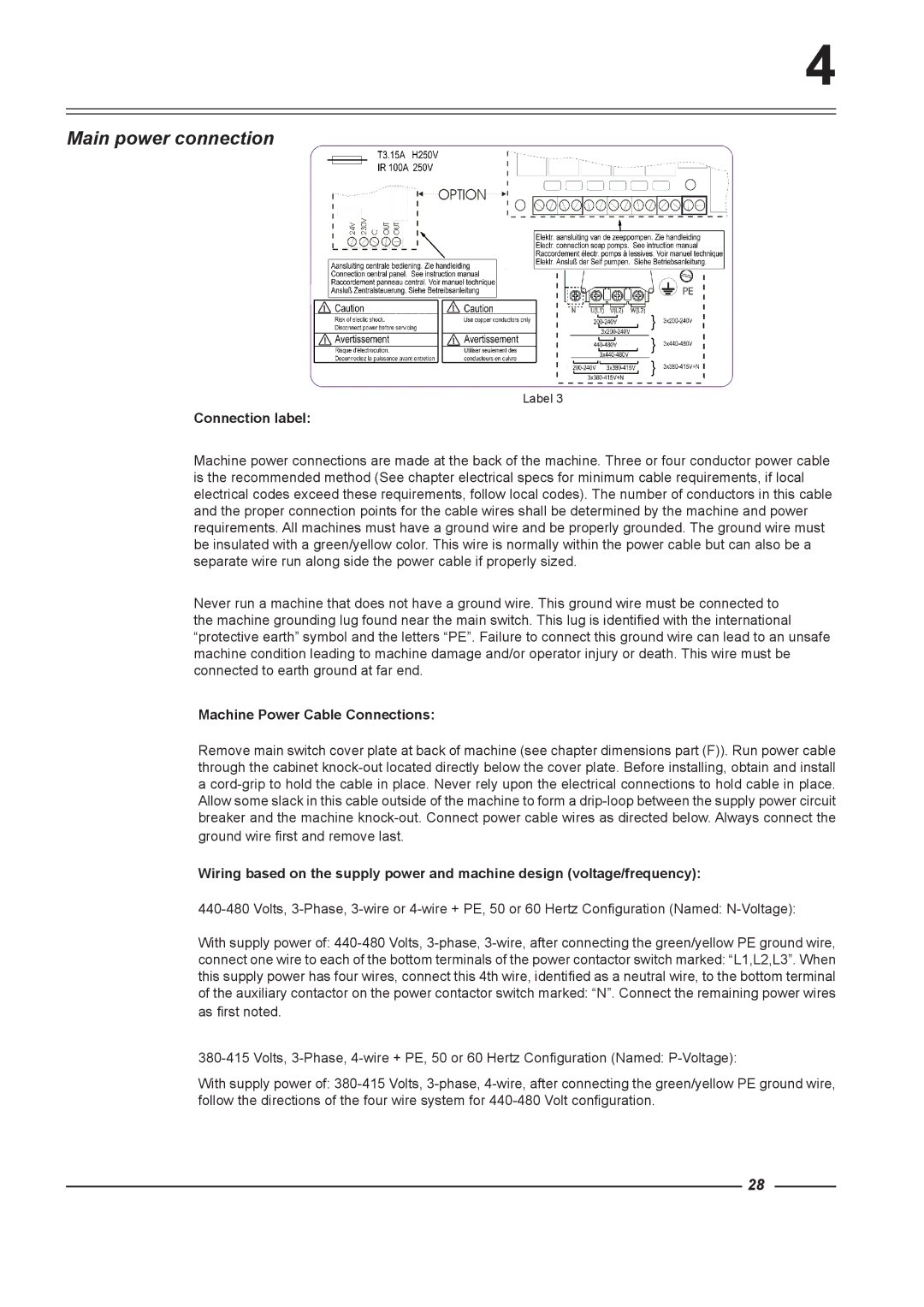
Label 3
Connection label:
Machine power connections are made at the back of the machine. Three or four conductor power cable is the recommended method (See chapter electrical specs for minimum cable requirements, if local electrical codes exceed these requirements, follow local codes). The number of conductors in this cable and the proper connection points for the cable wires shall be determined by the machine and power requirements. All machines must have a ground wire and be properly grounded. The ground wire must be insulated with a green/yellow color. This wire is normally within the power cable but can also be a separate wire run along side the power cable if properly sized.
Never run a machine that does not have a ground wire. This ground wire must be connected to the machine grounding lug found near the main switch. This lug is identified with the international “protective earth” symbol and the letters “PE”. Failure to connect this ground wire can lead to an unsafe machine condition leading to machine damage and/or operator injury or death. This wire must be connected to earth ground at far end.
Machine Power Cable Connections:
Remove main switch cover plate at back of machine (see chapter dimensions part (F)). Run power cable through the cabinet
ground wire first and remove last.
Wiring based on the supply power and machine design (voltage/frequency):
With supply power of:
connect one wire to each of the bottom terminals of the power contactor switch marked: “L1,L2,L3”. When this supply power has four wires, connect this 4th wire, identified as a neutral wire, to the bottom terminal of the auxiliary contactor on the power contactor switch marked: “N”. Connect the remaining power wires
as first noted.
With supply power of:
28