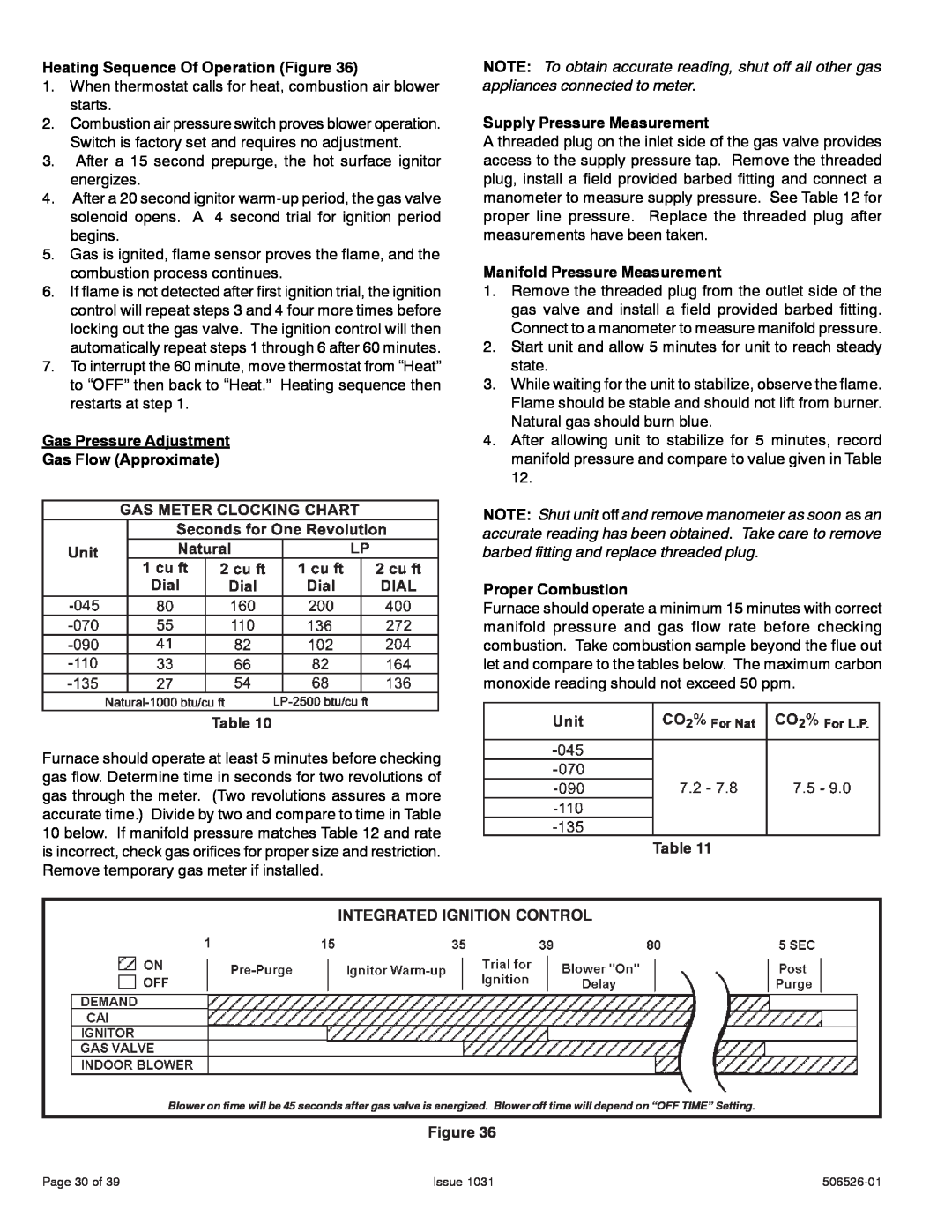
Heating Sequence Of Operation (Figure 36)
1.When thermostat calls for heat, combustion air blower starts.
2.Combustion air pressure switch proves blower operation. Switch is factory set and requires no adjustment.
3.After a 15 second prepurge, the hot surface ignitor energizes.
4.After a 20 second ignitor
5.Gas is ignited, flame sensor proves the flame, and the combustion process continues.
6.If flame is not detected after first ignition trial, the ignition control will repeat steps 3 and 4 four more times before locking out the gas valve. The ignition control will then automatically repeat steps 1 through 6 after 60 minutes.
7.To interrupt the 60 minute, move thermostat from “Heat” to “OFF” then back to “Heat.” Heating sequence then restarts at step 1.
Gas Pressure Adjustment
Gas Flow (Approximate)
Table 10
Furnace should operate at least 5 minutes before checking gas flow. Determine time in seconds for two revolutions of gas through the meter. (Two revolutions assures a more accurate time.) Divide by two and compare to time in Table 10 below. If manifold pressure matches Table 12 and rate is incorrect, check gas orifices for proper size and restriction. Remove temporary gas meter if installed.
NOTE: To obtain accurate reading, shut off all other gas appliances connected to meter.
Supply Pressure Measurement
A threaded plug on the inlet side of the gas valve provides access to the supply pressure tap. Remove the threaded plug, install a field provided barbed fitting and connect a manometer to measure supply pressure. See Table 12 for proper line pressure. Replace the threaded plug after measurements have been taken.
Manifold Pressure Measurement
1.Remove the threaded plug from the outlet side of the gas valve and install a field provided barbed fitting. Connect to a manometer to measure manifold pressure.
2.Start unit and allow 5 minutes for unit to reach steady state.
3.While waiting for the unit to stabilize, observe the flame. Flame should be stable and should not lift from burner. Natural gas should burn blue.
4.After allowing unit to stabilize for 5 minutes, record manifold pressure and compare to value given in Table 12.
NOTE: Shut unit off and remove manometer as soon as an accurate reading has been obtained. Take care to remove barbed fitting and replace threaded plug.
Proper Combustion
Furnace should operate a minimum 15 minutes with correct manifold pressure and gas flow rate before checking combustion. Take combustion sample beyond the flue out let and compare to the tables below. The maximum carbon monoxide reading should not exceed 50 ppm.
Table 11
INTEGRATED IGNITION CONTROL
Blower on time will be 45 seconds after gas valve is energized. Blower off time will depend on “OFF TIME” Setting.
Figure 36
Page 30 of 39 | Issue 1031 |