4.All pipe should be supported using the proper clamps and/or straps. These supports should be at least every four (4') feet.
5.All horizontal runs of pipe should have at least a 1/4" (in.) per foot of upward slope from the furnace to the vent terminal.
6.All runs of pipe should be as short as possible with as few turns as possible.
7.Seams should be tightly joined and checked for leaks.
8.The flue pipe must not extend into the chimney but be flush with the inside wall.
9.The chimney or vent pipe must extend at least three (3') feet above the highest point where it passes through a roof of a building and at least two (2') feet higher than any portion of a building within a horizontal distance of ten (10') feet. It shall also extend at least five (5') feet above highest connected equipment flue collar.
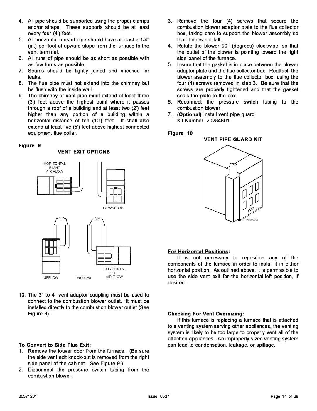
Figure 9
VENT EXIT OPTIONS
10.The 3" to 4" vent adaptor coupling must be used to connect to the combustion blower outlet. It must be installed directly to the combustion blower outlet (See Figure 8).
To Convert to Side Flue Exit:
1.Remove the louver door from the furnace. (Be sure the side vent exit
2.Disconnect the pressure switch tubing from the combustion blower.
3.Remove the four (4) screws that secure the combustion blower adaptor plate to the flue collector box, taking care to support the blower assembly so that it does not fall.
4.Rotate the blower 90° (degrees) clockwise, so that the outlet of the blower is pointing toward the right side panel of the furnace.
5.Insure that the gasket is in place between the blower adaptor plate and the flue collector box. Reattach the blower assembly to the flue collector box, using the four (4) screws removed in step 3. Be sure that the screws are properly tightened and that the gasket seals the plate to the box.
6.Reconnect the pressure switch tubing to the combustion blower.
7.(Optional) Install vent pipe guard. Kit Number 20284801.
Figure 10
VENT PIPE GUARD KIT
For Horizontal Positions:
It is not necessary to reposition any of the components of the furnace in order to install it in either horizontal position. As outlined above, it is permissible to use the side vent exit for the
Checking For Vent Oversizing:
If this furnace is replacing a furnace that is attached to a venting system serving other appliances, the venting system is likely to be too large to properly vent all of the attached appliances. An improperly sized venting system can lead to condensation, leakage, or spillage.
20571201 | Issue 0527 | Page 14 of 28 |