Manuals
/
Allied Air Enterprises
/
Household Appliance
/
Furnace
Allied Air Enterprises
Upflow specifications Furnace Wiring Specifications, Issue, Page 5 of
Models:
Downflow or Horizontal 2 Stage Heat Variable Speed Gas Fired Non-Condensing Warm Air Furnace
Upflow
1
5
28
28
Download
28 pages
32.15 Kb
1
2
3
4
5
6
7
8
<
>
Troubleshooting
Specifications
Install
Figure GAS CONTROL DIAGRAM
Manifold or Burner/Manifold Removal/Replacement
Issue
Adjusting Airflow
ElectronicAir Cleaner Connections
Typical Gas Service Connection
Flame Rollout Switch
Page 5
Image 5
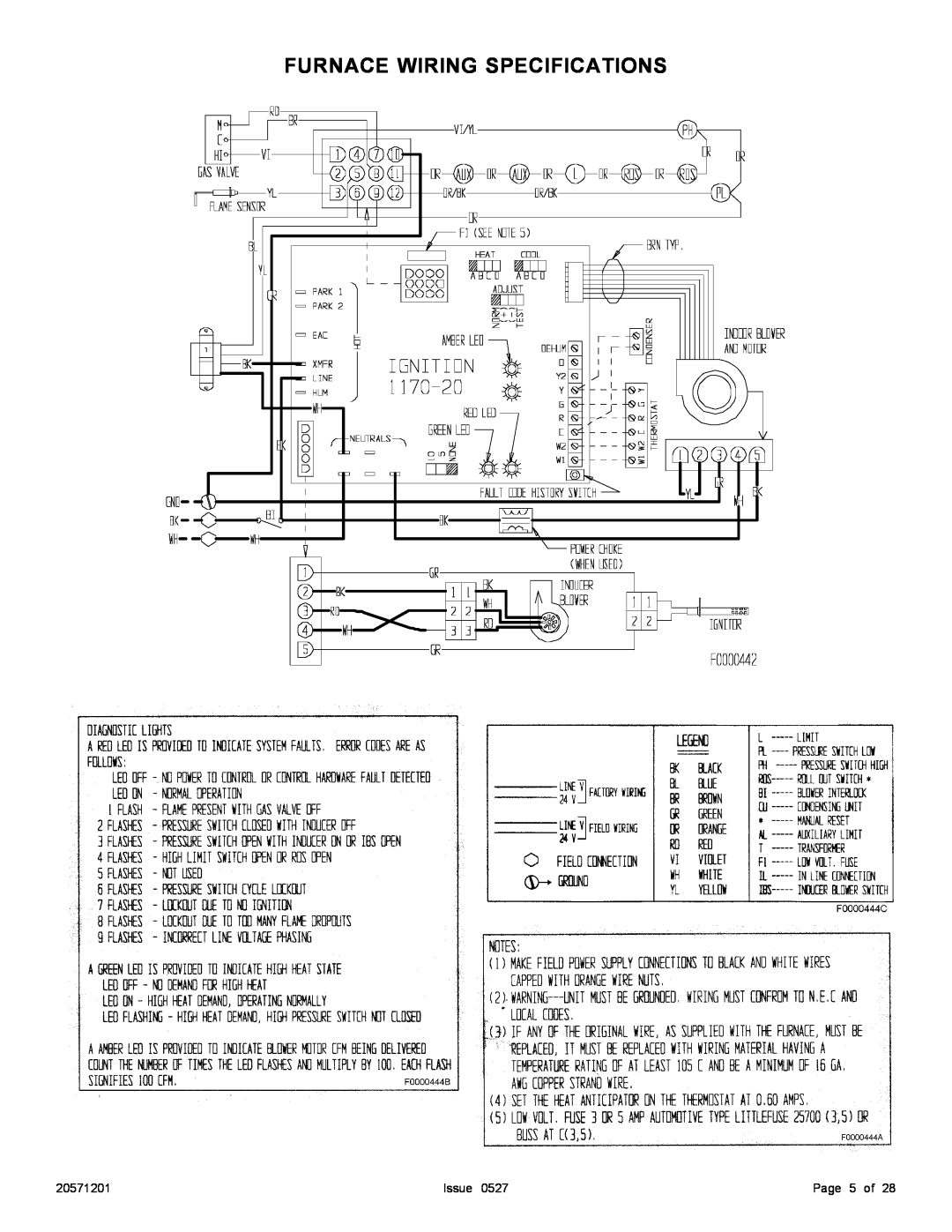
FURNACE WIRING SPECIFICATIONS
20571201
Issue 0527
Page 5 of 28
Page 4
Page 6
Page 5
Image 5
Page 4
Page 6
Contents
WHAT TO DO IF YOU SMELL GAS
TABLE OF CONTENTS
Page 2 of
SAFETY
Issue
Page 3 of
FURNACE SPECIFICATIONS
Issue
Adjusting Airflow
Page 5 of
FURNACE WIRING SPECIFICATIONS
Issue
Page 6 of
Issue
INTRODUCTION
INSTALLATION POSITIONS
LOCATION / PLACEMENT
This furnace may be installed on non-combustible
Figure HORIZONTAL LINE CONTACT
Adequate Ventilation and Combustion Air
AIR FOR COMBUSTION AND VENTILATION
Contaminated Combustion Air
CONFINED SPACE / OUTDOOR AIR
CONFINED SPACE / INDOOR AIR
FROM ATTIC
CONFINED SPACE / OUTDOOR AIR
CONFINED SPACE / OUTDOOR
AIR THROUGH HORIZONTAL DUCTS
DUCTING
Table SPECIAL BASE INSTALLATION
Ductwork Recommendation
Figure BOTTOM PANEL REMOVAL
VENTING
Pre-InstallationVent System Inspection
Filters
EXTERNAL FILTER RACK SIZE
Type B Vent
Masonry Chimney
Horizontal Venting
Table 4 AUXILIARY DRAFT INDUCERS
To Convert toSide Flue Exit
Figure VENT EXIT OPTIONS
Figure VENT PIPE GUARD KIT
For Horizontal Positions
CARBON MONOXIDE POISONING HAZARD
ELECTRICAL CONNECTIONS
Thermostat
Single Stage Thermostat Operation
GAS CONNECTIONS
TYPICAL GAS SERVICE CONNECTION
Figure AUTOMATIC HEAT STAGING JUMPER
FIRE OR EXPLOSION HAZARD
ElectronicAir Cleaner Connections
CONTROL BOARD & VARIABLE SPEED MOTOR FEATURES
Variable Speed Features
Circulating Airflow Adjustments
Cooling Mode
UNIT SEQUENCE OF OPERATION
HeresHow Your Heating System Works
Standby Mode
Manifold Pressure Adjustment
Figure GAS CONTROL DIAGRAM
STARTUP AND OPERATIONAL CHECKOUT
Figure TYPICAL FLAME APPEARANCE Main Burners
TABLE Gas Rate Cubic Feet per Hour
Determining Furnace Input - Natural Gas Only
Burner Orifice Sizing
Blower Adjustment Checkout
TABLE Burner Orifice Selection
Natural
Figure FLAME ROLLOUT SWITCH
Flame Rollout Switch
Pressure Switch Check
Issue
DIRECT IGNITION SYSTEM CONTROL
SEQUENCE OF OPERATION
SERVICING THE FURNACE
Manifold or Burner/Manifold Removal/Replacement
ELECTRICAL SHOCK, FIRE OR EXPLOSION HAZARD
Combustion Component Check
Lubricating Motors
Blower Removal/Replacement
Figure BLOWER REMOVAL AND REPLACEMENT
Fault Code History Button
Troubleshooting
High Heat State LED
CFM LED
Page 27 of
WIRING DIAGRAM
Issue
Page 28 of
Issue