Chapter 1: Overview
LEDs
Here are descriptions of the switch LEDs.
System LEDs
RJ-45 Port LEDs
&MODE LED SELECT Button
There are two system LEDs, the Power (PWR) LED and System (SYS) LED, as shown in Figure 8.
Figure 8. Power and System LEDs
The system LED states are described in Table 4.
Table 4. System LED States
LED | State | Description |
|
|
|
|
|
|
Power | Green | System is powered up (power on) |
|
|
|
| Off | System is not powered up (power off) |
|
|
|
SYS | Green | System is operational |
|
|
|
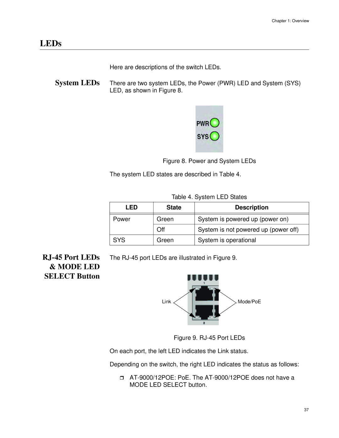
The
Link | Mode/PoE |
Figure 9. RJ-45 Port LEDs
On each port, the left LED indicates the Link status.
Depending on the switch, the right LED indicates the status as follows:
AT-9000/12POE: PoE. The AT-9000/12POE does not have a MODE LED SELECT button.
37
