Chapter 1: Overview
LEDs
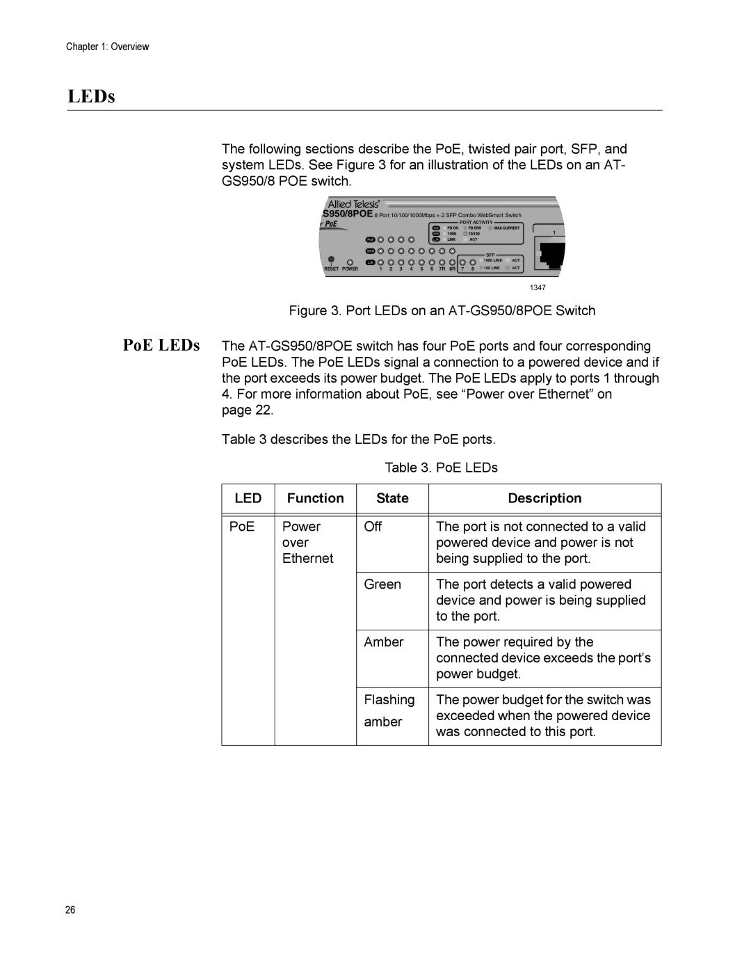
The following sections describe the PoE, twisted pair port, SFP, and system LEDs. See Figure 3 for an illustration of the LEDs on an AT- GS950/8 POE switch.
GS950/8POE 8 Port 10/100/1000Mbps + 2 SFP Combo WebSmart Switch
PORT ACTIVITY
1
ACT
SFP
![]() 1000 LINK
1000 LINK ![]() ACT
ACT
RESET POWER | 1 2 3 4 5 6 7R 8R 7 8 | 100 LINK | ACT |
1347
Figure 3. Port LEDs on an AT-GS950/8POE Switch
PoE LEDs The
4.For more information about PoE, see “Power over Ethernet” on page 22.
Table 3 describes the LEDs for the PoE ports.
Table 3. PoE LEDs
LED | Function | State | Description |
|
|
|
|
|
|
|
|
PoE | Power | Off | The port is not connected to a valid |
| over |
| powered device and power is not |
| Ethernet |
| being supplied to the port. |
|
|
|
|
|
| Green | The port detects a valid powered |
|
|
| device and power is being supplied |
|
|
| to the port. |
|
|
|
|
|
| Amber | The power required by the |
|
|
| connected device exceeds the port’s |
|
|
| power budget. |
|
|
|
|
|
| Flashing | The power budget for the switch was |
|
| amber | exceeded when the powered device |
|
| was connected to this port. | |
|
|
| |
|
|
|
|
26
