Chapter 1: Overview
Network Topologies
Power
Workgroup
Topology
This section describes the network topologies of the
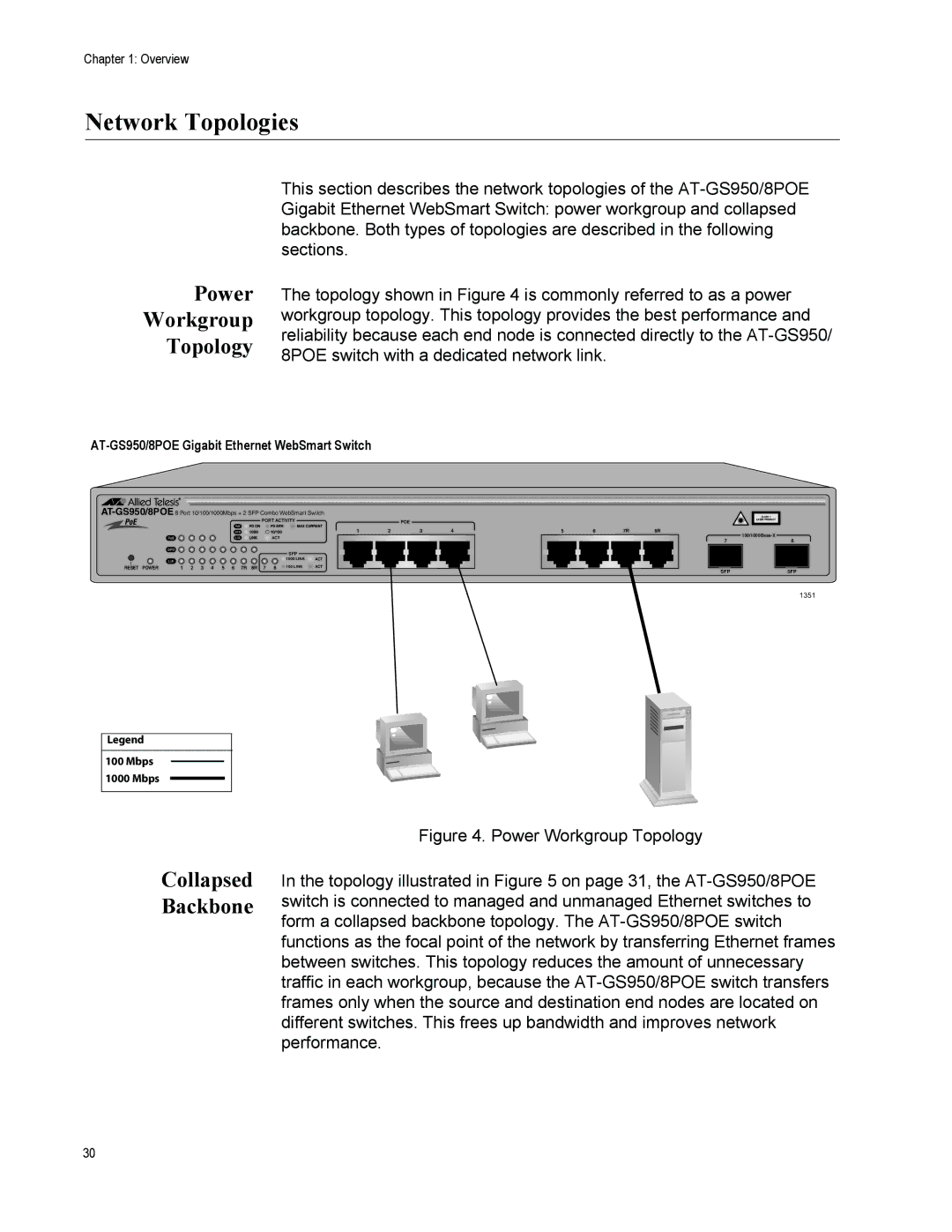
The topology shown in Figure 4 is commonly referred to as a power workgroup topology. This topology provides the best performance and reliability because each end node is connected directly to the
AT-GS950/8POE Gigabit Ethernet WebSmart Switch
PORT ACTIVITY | POE |
1234
ACT
SFP
![]() 1000 LINK
1000 LINK ![]() ACT
ACT
RESET POWER | 1 2 3 4 5 6 7R 8R 7 8 | 100 LINK | ACT |
CLASS 1
LASER PRODUCT
5 | 6 | 7R | 8R |
7 | 8 |
SFPSFP
1351
Legend
100Mbps
1000 Mbps
Collapsed
Backbone
Figure 4. Power Workgroup Topology
In the topology illustrated in Figure 5 on page 31, the AT-GS950/8POE switch is connected to managed and unmanaged Ethernet switches to form a collapsed backbone topology. The AT-GS950/8POE switch functions as the focal point of the network by transferring Ethernet frames between switches. This topology reduces the amount of unnecessary traffic in each workgroup, because the AT-GS950/8POE switch transfers frames only when the source and destination end nodes are located on different switches. This frees up bandwidth and improves network performance.
30