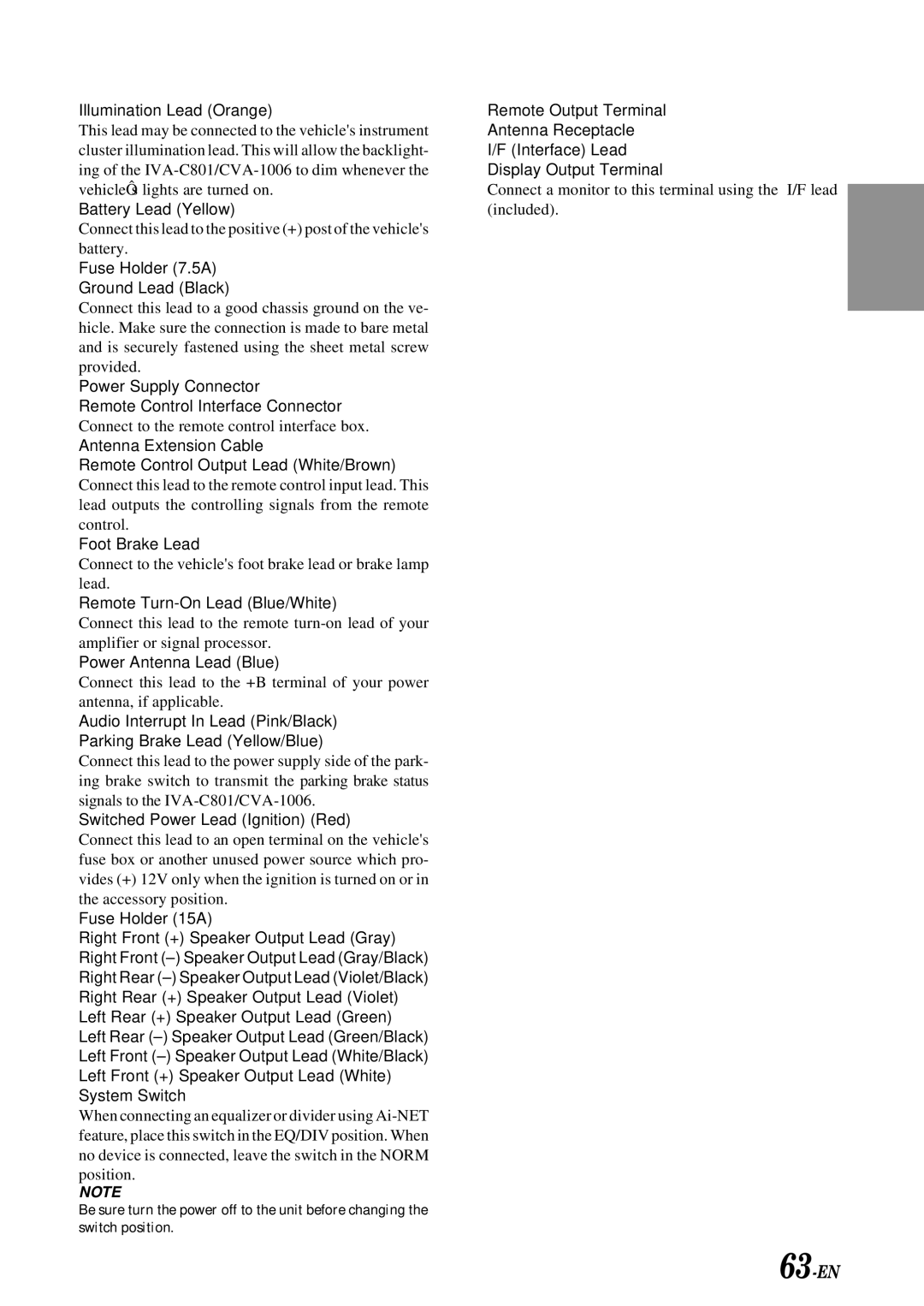
IVA-C801 specifications
The Alpine IVA-C801 is an innovative multimedia receiver that has redefined in-car entertainment by integrating advanced technology with user-friendly features. This versatile system blends high-performance audio playback with robust video capabilities, making it a perfect choice for audiophiles and casual listeners alike.One of the standout features of the IVA-C801 is its 7-inch wide touchscreen display. This TFT LCD screen offers exceptional resolution, which ensures crystal-clear visuals whether you're watching videos or navigating through menus. The screen is designed with a user-friendly interface, giving drivers easy access to their favorite apps, songs, and settings without taking their focus off the road.
The Alpine IVA-C801 supports a variety of media formats, accommodating CD, DVD, and MP3 playback. This flexibility allows users to enjoy their favorite music and movies exactly how they want. Additionally, the receiver is equipped with a built-in AM/FM tuner and is compatible with HD Radio, providing crystal-clear reception of local stations.
Another crucial aspect of the IVA-C801 is its Bluetooth connectivity. This feature enables hands-free calling and wireless streaming, allowing users to enjoy their playlists or take calls without the hassle of tangled wires. The unit can also sync with smartphones, providing access to apps such as Spotify and Pandora directly from the touchscreen.
For those who prioritize sound quality, the IVA-C801 includes a powerful built-in amplifier and a range of audio tuning options. The system features advanced equalization settings, allowing users to customize the sound output to their personal preferences for a richer listening experience. The receiver is also compatible with Alpine's array of premium speakers, enhancing the audio fidelity even further.
Additional technology highlights of the IVA-C801 include a rear-view camera input for enhanced safety during parking maneuvers, as well as a video output for connecting to additional screens. The intuitive layout and customizable backgrounds of the interface make the receiver a standout in terms of both aesthetics and functionality.
In conclusion, the Alpine IVA-C801 is not just a receiver but a comprehensive multimedia solution for any vehicle. Its blend of high-quality audio and video performance, combined with cutting-edge features like Bluetooth connectivity and user-friendly interface, positions it as an ideal choice for those looking to elevate their driving experience. With the IVA-C801, Alpine continues to set the standard in automotive entertainment, making every drive enjoyable and engaging.

