IP 710 specifications
The AltiGen Communications IP710 is a versatile and advanced VoIP phone designed for businesses seeking effective communication solutions. This device is part of AltiGen’s extensive product range, which emphasizes quality, reliability, and user-friendly features. The IP710 is engineered to enhance productivity and streamline collaboration in modern workplace environments.One of the standout features of the AltiGen IP710 is its high-definition audio quality, which ensures crystal-clear voice communication. This is pivotal in business settings, where clarity can significantly impact the effectiveness of conversations. The phone is equipped with wideband audio technology, allowing it to deliver superior sound quality over standard telephony systems. Additionally, echo cancellation and noise suppression technologies enhance the user experience, making discussions more pleasant and less prone to interruptions.
The IP710 includes a large, backlit display, providing users easy access to essential information and features. The intuitive user interface supports easy navigation, enabling users to manage calls effectively. With programmable function keys, users can customize their phone according to their specific needs, facilitating quick access to frequently used features. The phone also has multiple lines and SIP account support, allowing users to handle several calls simultaneously, which is particularly beneficial for busy professionals and receptionists.
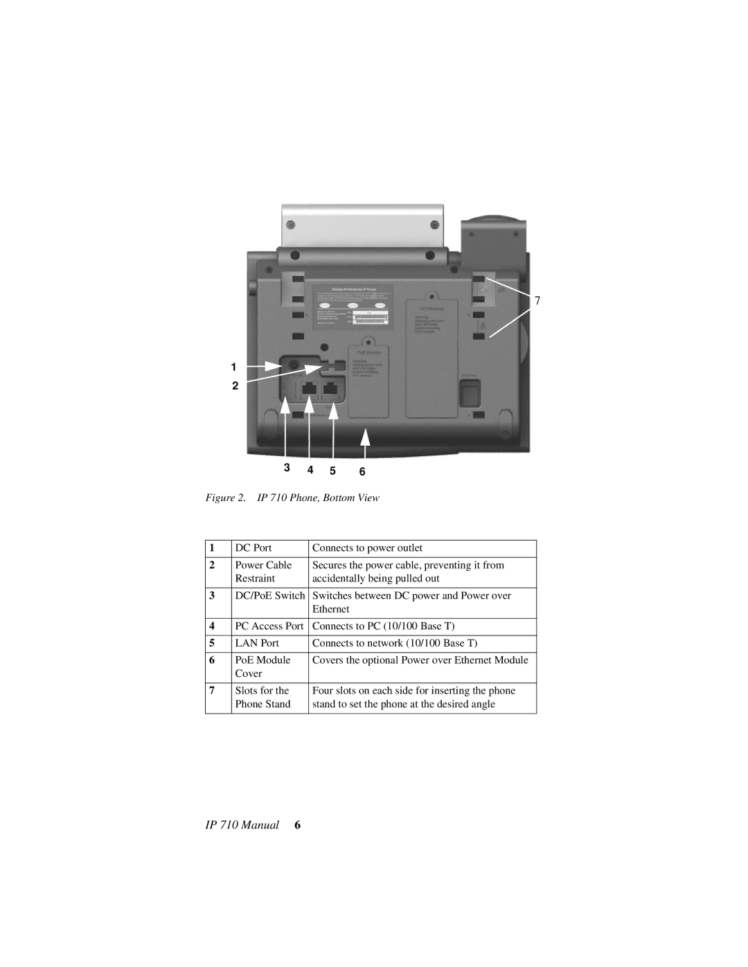
In terms of connectivity, the AltiGen IP710 is compatible with various network environments and can be easily integrated into existing IT infrastructures. Its Power over Ethernet (PoE) capability simplifies installation by eliminating the need for a separate power supply, making it flexible for deployment in diverse settings.
Security features have also been taken into account, with support for encrypted Voice over IP (VoIP) protocols, ensuring that calls remain secure and private. This is a vital consideration for organizations that handle sensitive information.
The AltiGen IP710 is designed with the modern workplace in mind, supporting various communication protocols and offering comprehensive features like call forwarding, conferencing, and voicemail. Its adaptability ensures that it can cater to the unique needs of different business models.
In summary, the AltiGen IP710 VoIP phone combines advanced audio technology, user-friendly design, and robust connectivity options, making it a valuable asset for any organization striving to enhance its communication capabilities. With its emphasis on security and flexibility, this device exemplifies innovation in business telephony.

