3.Electrical Connections
NOTE: A wiring diagram is included with each dryer and is affixed to the rear upper right guard/panel of the dryer.
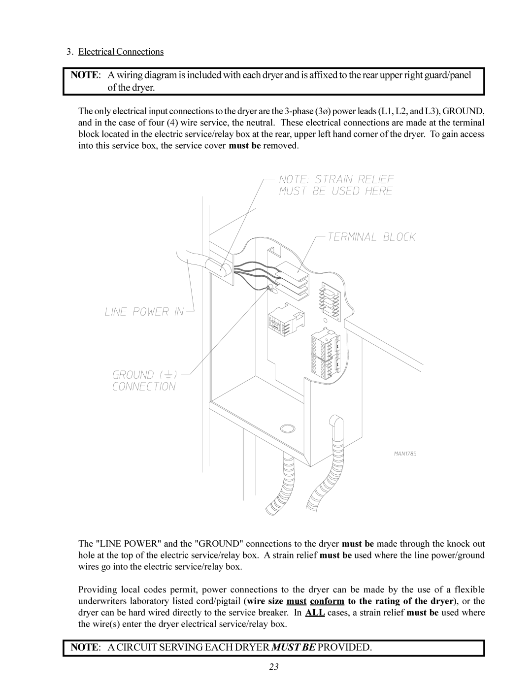
The only electrical input connections to the dryer are the
The "LINE POWER" and the "GROUND" connections to the dryer must be made through the knock out hole at the top of the electric service/relay box. A strain relief must be used where the line power/ground wires go into the electric service/relay box.
Providing local codes permit, power connections to the dryer can be made by the use of a flexible underwriters laboratory listed cord/pigtail (wire size must conform to the rating of the dryer), or the dryer can be hard wired directly to the service breaker. In ALL cases, a strain relief must be used where the wire(s) enter the dryer electrical service/relay box.
NOTE: A CIRCUIT SERVING EACH DRYER MUST BE PROVIDED.
23