Installation and Operation Guide

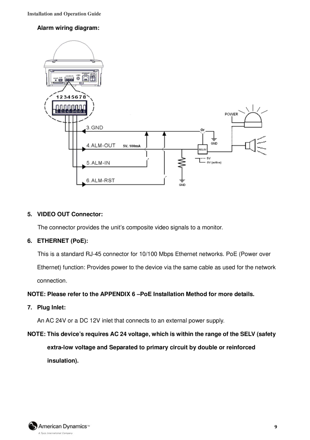
Alarm wiring diagram:

5.VIDEO OUT Connector:

The connector provides the unit’s composite video signals to a monitor.

6.ETHERNET (PoE):

This is a standard RJ-45 connector for 10/100 Mbps Ethernet networks. PoE (Power over Ethernet) function: Provides power to the device via the same cable as used for the network connection.

NOTE: Please refer to the APPENDIX 6 –PoE Installation Method for more details.

7.Plug Inlet:

An AC 24V or a DC 12V inlet that connects to an external power supply.

NOTE: This device’s requires AC 24 voltage, which is within the range of the SELV (safety

extra-low voltage and Separated to primary circuit by double or reinforced insulation).

9

Page 9
Image 9
American Dynamics 8200-2646-02 B0 manual Alarm wiring diagram Video OUT Connector, Ethernet PoE, Plug Inlet