whenever maintenance adjustment or service is required
For Your Safety
RESIDENTIAL GAS WATER HEATERS
Instruction Manual
table of contents
safe installation, use and service
APPROVALS
DANGER
Precautions
general safety information
Improper installation, use and service may result in property damage
Explosion Hazard
general safety information
Fire or Explosion Hazard
General Safety Information
Breathing Hazard - Carbon Monoxide Gas
Electrical Shock Hazard
introduction
Preparing For The Installation
Abbreviations Used
Qualifications
REPLACEMENT PARTS AND DELIMING PRODUCTS
features and components
Get To Know Your Water Heater - Gas Models
Control Assembly
Rough In Dimensions
installation consideration
Table 1 - Rough-In-Dimensions
Table 2 - Capacity, Gas and Electrical Characteristics
Locating The Water Heater
Property Damage Hazard
Combustion Air and Ventilation
Insulation Blankets
Unconfined Space
Fresh Air Openings For Confined Spaces
Confined Space
Outdoor Air Through Two Openings
Outdoor Air Through One Opening
Air From Other Indoor Spaces
Outdoor Air Through Two Horizontal Ducts
Power Supply
installing the new water heater
Chemical Vapor Corrosion
Water Piping
Dishwashing Machines
Mixing Valves
Space Heating and Potable Water System
Time to Produce 2nd & 3rd
Closed Water Systems
Thermal Expansion
T & P Valve and Pipe Insulation if supplied
Explosion Hazard
Water Damage Hazard
Temperature-Pressure Relief Valve
T&P Valve Discharge Pipe Requirements
Supply Gas Regulator
Gas Piping
Condensate Piping
SEDIMENT TRAPS
Filling the Water Heater
High Altitude Installations
If using 2” inch vent pipe
Venting
If using 3” inch vent pipe
VENT PIPE TERMINATION
VENT TERMINAL INSTALLATION, SIDEWALL
INSTALLATION OF VENT SYSTEM
Installation of Carbon Monoxide Detectors
Installation Requirements - Commonwealth of Massachusetts
Commonwealth of Massachusetts
Approved Carbon Monoxide Detectors
POWER VENT
Termination Clearances Sidewall Power Vent
Termination Clearances Sidewall Direct Vent
SEQUENCE OF INSTALLATIONS, FIGURE 15A
Installation Sequence
Vent Termination - Figure 15A DIRECT VENT terminal installation
Figure 15B
Flat Roof Installation
VERTICAL VENT TERMINAL INSTALLATION
SAFETY CONSIDERATIONS
Concentric vent installation
INSTALLATION PROCEDURE 1 ROOF TERMINATION, see Figure
Table 6 - KIT COMPONENTS
CONCENTRIC TERMINATION FLAT ROOF CLEARANCE
PROCEDURE 2 SIDE WALL TERMINATION, see Figure
Figure 23A
MULTI-CONCENTRIC VENT TERMINATIONS
direct vent diagram
RECOMMENDED BRUSH* SIZE FOR PRIMER AND CEMENT APPLICATIONS
Vent Pipe Preparation
1. INITIAL PREPARATION
2. SELECTION OF MATERIALS
STEP E F. Joint assembly
D. Inspection, cleaning, priming
STEP F G. Cleanup and joint movement
B. Deburring
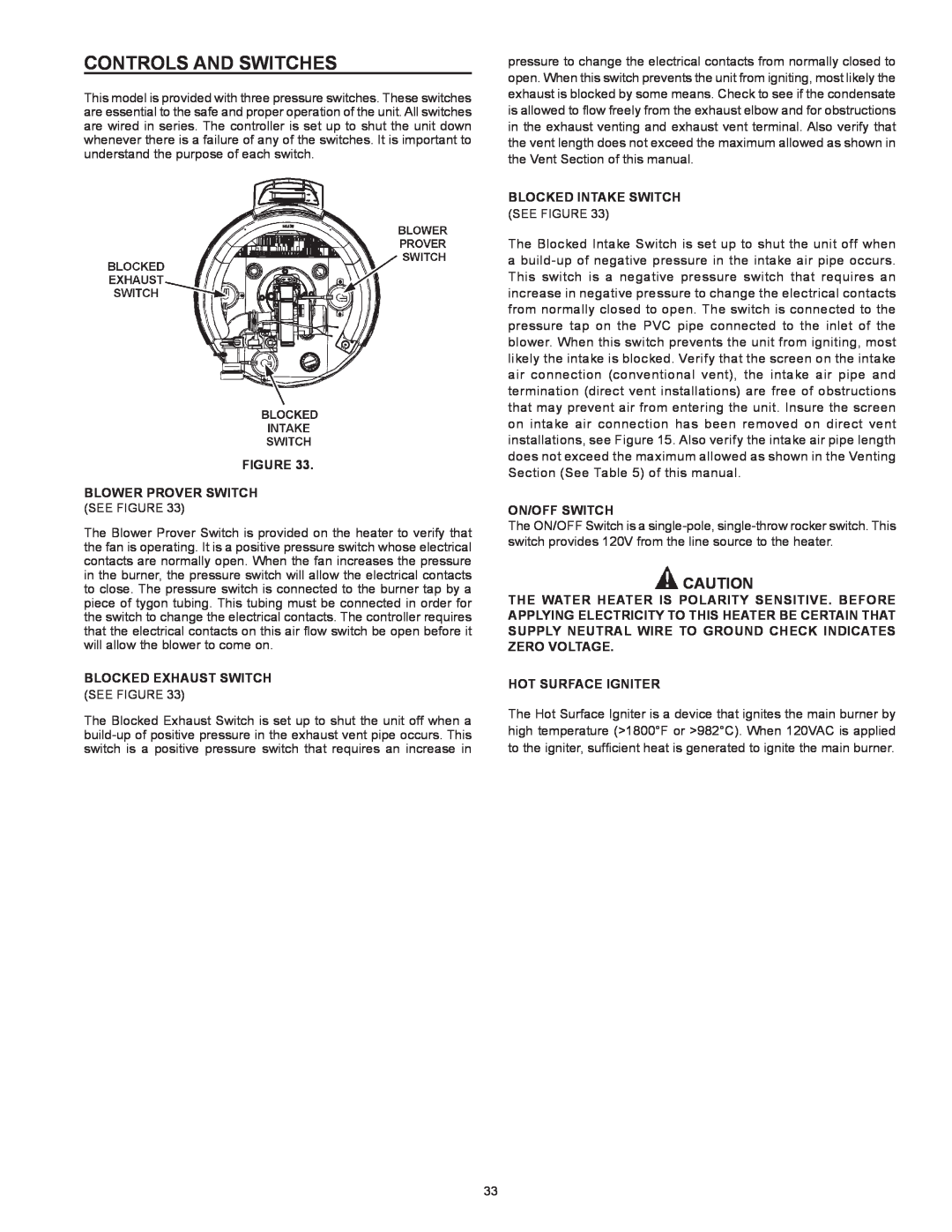
BLOWER PROVER SWITCH
Controls and Switches
BLOCKED EXHAUST SWITCH
BLOCKED INTAKE SWITCH
WIRE TO GROUND CHECK INDICATES ZERO VOLTAGE
Power Vent Wiring Schematic - Figure
THIS WATER HEATER IS POLARITY SENSITVE BEFORE APPLYING
ELECTRICITY TO THIS HEATER BE CERTAIN THAT SUPPLY NEUTRAL
OPERATING INSTRUCTIONS
FOR YOUR SAFETY READ BEFORE LIGHTING
TO TURN OFF GAS TO APPLIANCE
WARNING TURN OFF ALL ELECTRIC POWER BEFORE SERVICING
HI LIMIT SWITCH ECO
temperature regulation
Time to Produce
2nd & 3rd Degree
control system operation
adjust user settings
Operating Set Point
120F
Icon
Description
Status Icons
Menu
State
Operating States
Control System Menus
MENU
User Settings & Control System Menus
HELP
Main Menu
Heater Status
140F
Heater Information
Display Settings
Temperature Units
Backlight Delay
Fault Occurrence
Fault History
Restore Factory Defaults
Blocked Exhaust
Show Contact Information
Service Contact Information
Change Contact Name
Current Contact Info
Start Up Conditions
for your information
Operational Conditions
SMOKE/ODOR
Venting System Inspection
periodic maintenance
Anode Rod Inspection
Temperature-Pressure Relief Valve Operation
Draining and Flushing
Service
Burn harzard Hot water discharge
Keep hands clear of drain valve discharge
Temperature-Pressure Relief Valve Test
maintenance
leakage checkpoints
Installation Checklist
troubleshooting
Water Heater Location
Venting
YESNO
Sequence Of Operation Flow Chart
Fault and Alert Conditions
Operational Problems
Burn Hazard
Replacement Parts
Electrical Shock Hazard
Resetting Control System Lock Outs
Diagnostic Checks
Ignition Failure
AC Reversed
Low Igniter Current
Blocked Exhaust
Blower Prover Open
Blower Prover Failure
Blocked Air Intake
Energy Cut Out ECO
Page
Page
Page
SERVICE AND LABOR RESPONSIBILITY
LIMITED RESIDENTIAL GAS WARRANTY
CLAIM PROCEDURE
CONDITIONS AND EXCEPTIONS
American Water Heater Product Service and Support
PO Box 1597, 500 Princeton Road Johnson City, TN
Copyright 2011 American Water Heaters. All rights reserved