Termination Clearances Sidewall Direct Vent
|
|
|
|
|
| DIRECT VENT |
|
|
|
| ||||
|
|
|
| (using outdoor air for combustion) |
|
|
| |||||||
| EXTERIOR CLEARANCES FOR SIDEWALL VENT TERMINATION |
|
| |||||||||||
|
|
|
|
|
| G |
|
|
|
|
|
|
|
|
|
|
|
|
|
| V |
|
|
|
|
|
|
|
|
D |
|
|
|
|
| A |
|
|
|
|
| H |
|
|
|
|
|
|
|
|
|
|
|
|
|
|
| ||
vE |
|
|
|
|
|
|
|
|
|
|
|
|
| |
L | B |
|
|
|
|
|
|
|
|
|
|
|
|
|
| v |
|
|
|
|
|
|
|
| B |
|
|
|
|
|
|
|
| C |
| B |
|
|
| V |
|
|
| |
|
|
|
|
|
|
|
| FIXED |
|
|
| |||
|
|
|
|
|
|
|
| E |
|
|
| |||
|
|
| V | FIXED |
| V |
| OPERABL | CLOSED |
| M |
| X | |
|
|
|
|
|
|
|
| |||||||
|
|
| CLOSED |
|
|
|
|
|
|
| V | |||
|
|
|
|
|
|
|
|
|
|
| ||||
|
|
|
|
|
|
|
|
|
|
|
|
| ||
|
|
|
| OPERABL | E |
|
|
|
| X |
|
|
| |
|
|
| V | B |
| V |
|
|
|
|
| |||
|
| F |
|
|
|
|
|
|
|
| ||||
|
|
|
| B |
| J |
|
|
| K | ||||
|
|
|
|
|
|
|
|
|
| |||||
|
|
|
|
|
| A |
|
|
|
| ||||
|
|
|
|
|
|
|
|
|
|
| ||||
|
|
|
|
|
|
|
|
|
|
|
| |||
|
|
|
|
|
|
|
|
|
|
|
|
|
| |
|
|
|
| B |
|
|
|
|
|
|
|
|
|
|
V | VENT TERMINAL | X AIR SUPPLY INLET |
| AREA WHERE TERMINAL IS NOT PERMITTED | ||||||||||
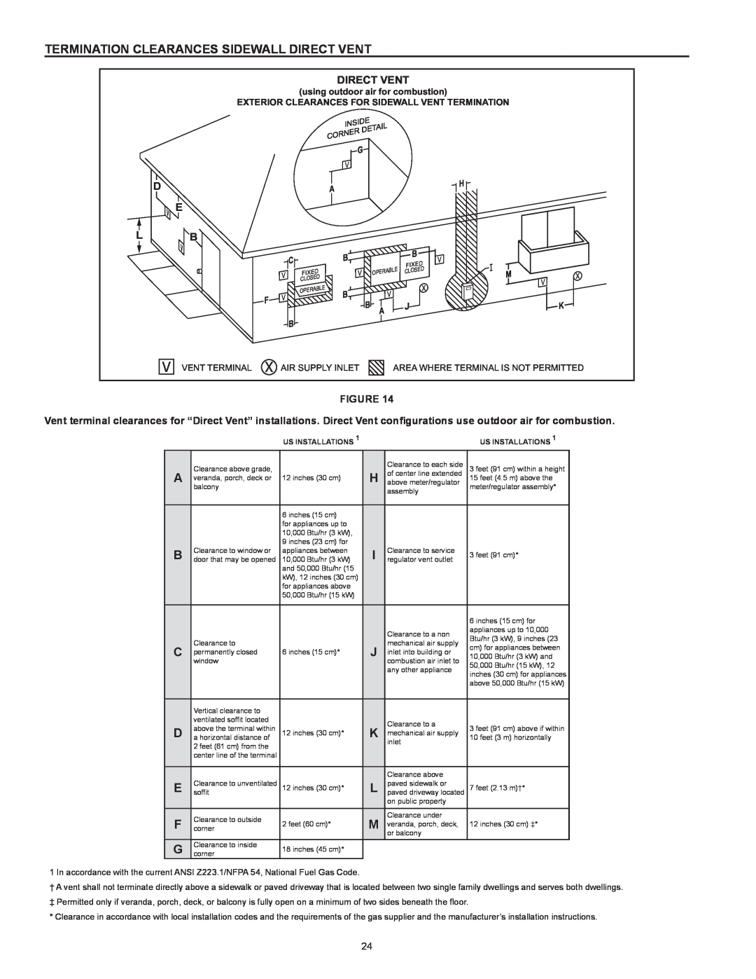
Figure 14
Vent terminal clearances for “Direct Vent” installations. Direct Vent configurations use outdoor air for combustion.
|
| US Installations 1 |
|
| US Installations 1 | |
| Clearance above grade, |
|
| Clearance to each side | 3 feet (91 cm) within a height | |
A | veranda, porch, deck or | 12 inches (30 cm) | H | of center line extended | 15 feet (4.5 m) above the | |
above meter/regulator | ||||||
| balcony |
|
| assembly | meter/regulator assembly* | |
|
|
|
|
| ||
|
|
|
|
|
| |
|
| 6 inches (15 cm) |
|
|
| |
|
| for appliances up to |
|
|
| |
|
| 10,000 Btu/hr (3 kW), |
|
|
| |
|
| 9 inches (23 cm) for |
|
|
| |
B | Clearance to window or | appliances between | I | Clearance to service | 3 feet (91 cm)* | |
door that may be opened | 10,000 Btu/hr (3 kW) | regulator vent outlet | ||||
|
| and 50,000 Btu/hr (15 |
|
|
| |
|
| kW), 12 inches (30 cm) |
|
|
| |
|
| for appliances above |
|
|
| |
|
| 50,000 Btu/hr (15 kW) |
|
|
| |
|
|
|
|
|
| |
|
|
|
|
| 6 inches (15 cm) for | |
|
|
|
| Clearance to a non | appliances up to 10,000 | |
|
|
|
| Btu/hr (3 kW), 9 inches (23 | ||
| Clearance to |
|
| mechanical air supply | ||
C |
| J | cm) for appliances between | |||
permanently closed | 6 inches (15 cm)* | inlet into building or | ||||
10,000 Btu/hr (3 kW) and | ||||||
| window |
|
| combustion air inlet to | 50,000 Btu/hr (15 kW), 12 | |
|
|
|
| any other appliance | ||
|
|
|
| inches (30 cm) for appliances | ||
|
|
|
|
| ||
|
|
|
|
| above 50,000 Btu/hr (15 kW) | |
|
|
|
|
|
| |
| Vertical clearance to |
|
|
|
| |
| ventilated soffit located |
|
| Clearance to a |
| |
D | above the terminal within | 12 inches (30 cm)* | K | 3 feet (91 cm) above if within | ||
mechanical air supply | ||||||
a horizontal distance of | 10 feet (3 m) horizontally | |||||
| 2 feet (61 cm) from the |
|
| inlet |
| |
| center line of the terminal |
|
|
|
| |
|
|
|
|
|
| |
|
|
|
| Clearance above |
| |
E | Clearance to unventilated | 12 inches (30 cm)* | L | paved sidewalk or | 7 feet (2.13 m)†* | |
soffit | paved driveway located | |||||
|
|
|
| on public property |
| |
|
|
|
|
|
| |
F | cornerClearance to outside |
| M | Clearance under |
| |
2 feet (60 cm)* | veranda, porch, deck, | 12 inches (30 cm) ‡* | ||||
|
|
|
| or balcony |
| |
G | cornerClearance to inside | 18 inches (45 cm)* |
|
|
|
1 In accordance with the current ANSI Z223.1/NFPA 54, National Fuel Gas Code.
†A vent shall not terminate directly above a sidewalk or paved driveway that is located between two single family dwellings and serves both dwellings.
‡ Permitted only if veranda, porch, deck, or balcony is fully open on a minimum of two sides beneath the floor.
* Clearance in accordance with local installation codes and the requirements of the gas supplier and the manufacturer’s installation instructions.
24