Connection and Wiring
Connection and Wiring
Device DIP Switch
The
After setting the AXlink device number, remove and reconnect the AXlink connector on the
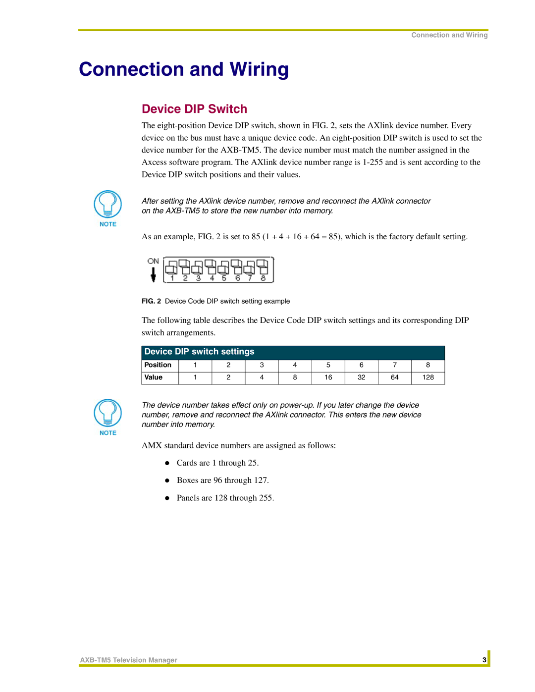
As an example, FIG. 2 is set to 85 (1 + 4 + 16 + 64 = 85), which is the factory default setting.
FIG. 2 Device Code DIP switch setting example
The following table describes the Device Code DIP switch settings and its corresponding DIP switch arrangements.
Device DIP switch settings
Position | 1 | 2 | 3 | 4 | 5 | 6 | 7 | 8 |
|
|
|
|
|
|
|
|
|
Value | 1 | 2 | 4 | 8 | 16 | 32 | 64 | 128 |
|
|
|
|
|
|
|
|
|
The device number takes effect only on
AMX standard device numbers are assigned as follows:
!Cards are 1 through 25.
!Boxes are 96 through 127.
!Panels are 128 through 255.
3 |
| |
|
|
|
