PWR
GND
PWR
AXP
AXM
GND
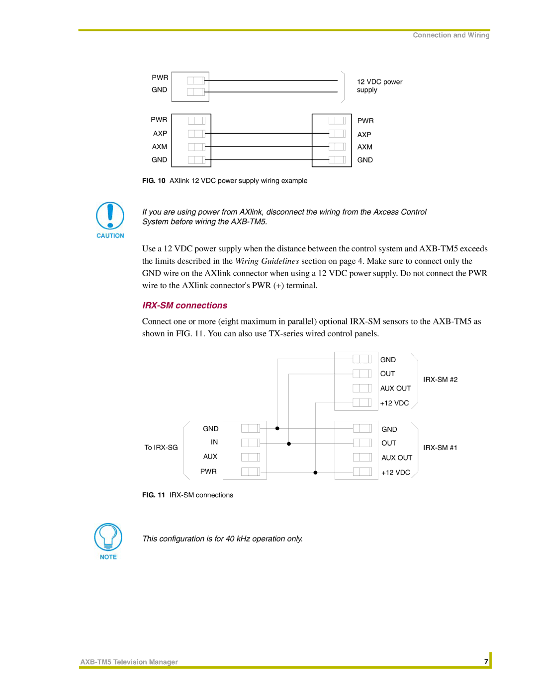
FIG. 10 AXlink 12 VDC power supply wiring example
Connection and Wiring
12 VDC power supply
PWR
AXP
AXM
GND
If you are using power from AXlink, disconnect the wiring from the Axcess Control System before wiring the
Use a 12 VDC power supply when the distance between the control system and
IRX-SM connections
Connect one or more (eight maximum in parallel) optional
GND
OUT
AUX OUT
+12 VDC
GND |
| GND |
IN |
| OUT |
To |
| |
AUX |
| AUX OUT |
PWR |
| +12 VDC |
FIG. 11 |
|
|
|
|
This configuration is for 40 kHz operation only.
7 |
| |
|
|
|