Connection and Wiring
For additional information concerning the IR emitter, refer to the IR Sensors and
Receivers instruction manual.
4.Attach the IR shield, with IR emitter diode, to the television IR window, ensuring that the IR emitter diode is properly positioned in the television input IR window.
5.Press firmly to activate the
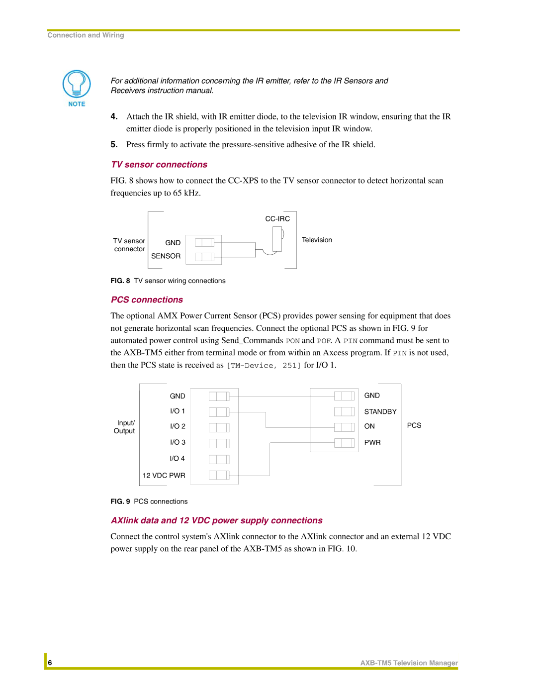
TV sensor connections
FIG. 8 shows how to connect the CC-XPS to the TV sensor connector to detect horizontal scan frequencies up to 65 kHz.
TV sensor | GND |
connector | SENSOR |
|
FIG. 8 TV sensor wiring connections
Television
PCS connections
The optional AMX Power Current Sensor (PCS) provides power sensing for equipment that does not generate horizontal scan frequencies. Connect the optional PCS as shown in FIG. 9 for automated power control using Send_Commands PON and POF. A PIN command must be sent to the
Input/ Output
GND
I/O 1
I/O 2
I/O 3
I/O 4 12 VDC PWR
GND
STANDBY
ON
PWR
PCS
FIG. 9 PCS connections
AXlink data and 12 VDC power supply connections
Connect the control system's AXlink connector to the AXlink connector and an external 12 VDC power supply on the rear panel of the
| 6 | |
|
|
|