Connection and Wiring
Wiring the Rear Panel
Preparing/connecting captive wires
You will need a wire stripper and flat-blade screwdriver to prepare and connect the captive wires.
Never pre-tin wires for compression-type connections.
Do not connect power to the AXB-TM5 until the wiring is complete. If you are using power from AXlink, disconnect the wiring from the control system before wiring the AXB-TM5. If you are using an optional 12 VDC power supply, apply power to the AXB-TM5 only after installation is complete.
1.Strip 0.25 inch of wire insulation off all wires.
2.Insert each wire into the appropriate opening on the connector according to the wiring diagrams and connector types described in this section.
3.Do not tighten the screws excessively; doing so may strip the threads and damage the connector.
Wiring Guidelines
The AXB-TM5 requires 12 VDC power to operate properly. The power can be supplied by the AMX system's AXlink cable or with an optional 12 VDC power supply. The maximum wiring distance between the control system and AXB-TM5 is determined by power consumption, supplied voltage, and the wire gauge used for the cable. The following table lists wire sizes and the maximum lengths allowable between the AXB-TM5 and the control system. The maximum wiring lengths are based on a minimum of 13.5 volts available at the control system's power supply.
Wiring Guidelines @ 200 mA
Wire size | Maximum wiring length |
| |
18 AWG | 586.55 feet (178.78 meters) |
| |
20 AWG | 371.29 feet (113.17 meters) |
| |
22 AWG | 231.48 feet (70.56 meters) |
| |
24 AWG | 145.91 feet (44.47 meters) |
| |
If the AXB-TM5 is installed farther away from the control system than recommended in the above table, connect an external 12 VDC power supply to the two-pin PWR connector on the rear panel.
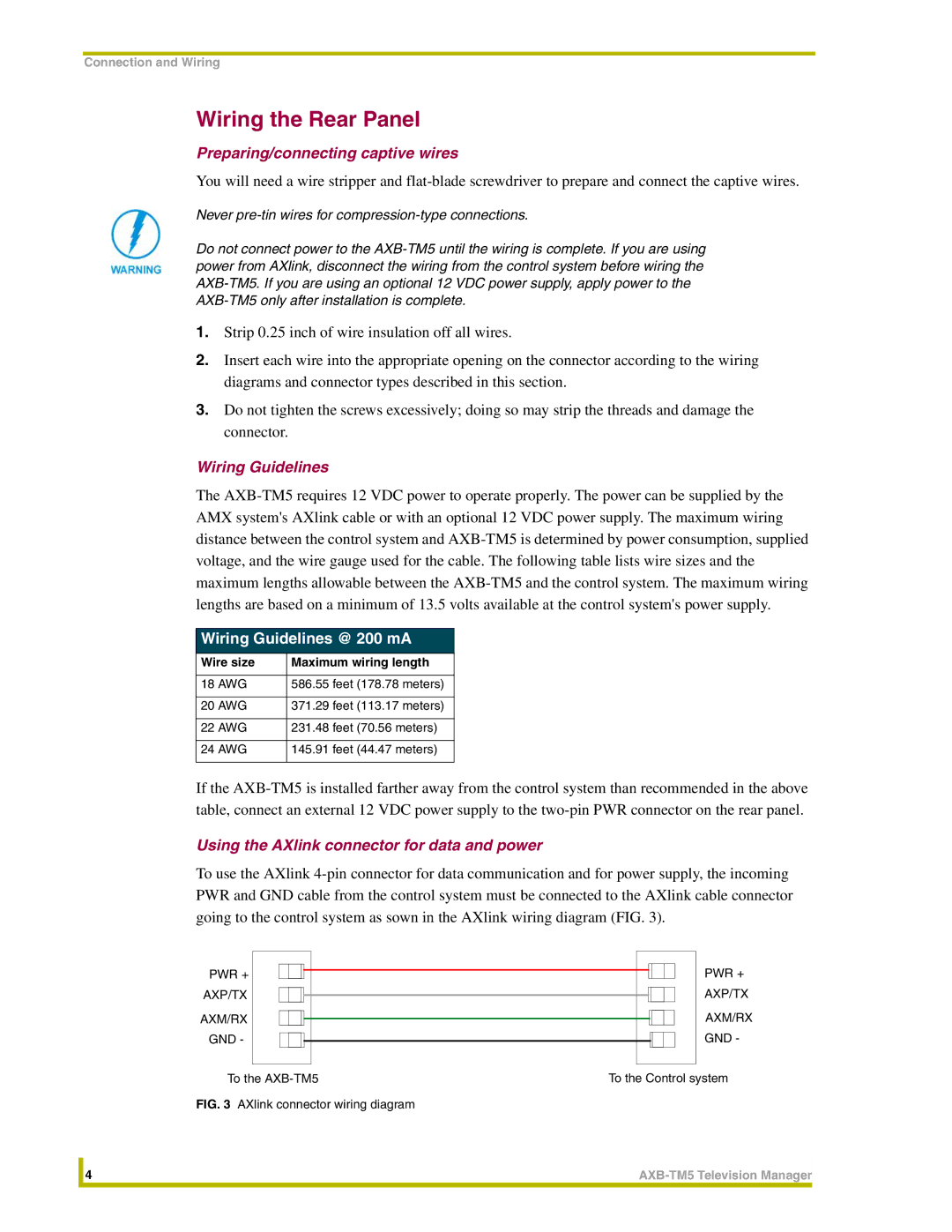
Using the AXlink connector for data and power
To use the AXlink 4-pin connector for data communication and for power supply, the incoming PWR and GND cable from the control system must be connected to the AXlink cable connector going to the control system as sown in the AXlink wiring diagram (FIG. 3).
PWR + | | | | | | | | | | | PWR + |
| | | | | | | | | |
AXP/TX | | | | | | | | | | | AXP/TX |
| | | | | | | | | |
| | | | | | | | | |
AXM/RX | | | | | | | | | | | AXM/RX |
| | | | | | | | | |
| | | | | | | | | |
GND - | | | | | | | | | | | GND - |
| | | | | | | | | |
| | | | | | | | | |
| | | | | | | | | | | |
To the AXB-TM5 | To the Control system |
FIG. 3 AXlink connector wiring diagram | | | | | | |
| 4 | AXB-TM5 Television Manager |
| | |