6.Connect the appropriate connector(s) from the power supply to the hard drive(s).
2.4 5.25” Device Installation
There are three external 5.25” drive bays.
1.Looking from the rear of the case you can see metal grills covering the 5.25” drive bays. Carefully push a screwdriver through the metal grill and gently push the plastic drive bay cover outwards until it comes off.
2.Using your hands, twist the metal plate back and forth until it breaks off.
Note: Don’t break off the metal grills covering the drive bays that you are not using now. Be careful of the newly exposed metal where the grill was attached, as these areas are likely to be sharp.
3.Fasten the 5.25” device into the drive bay with the screws provided.
4.Repeat the same procedure for other devices.
5.Connect the appropriate connector from the power supply to the device.
Connecting the Front I/O Ports
3.1 USB 2.0
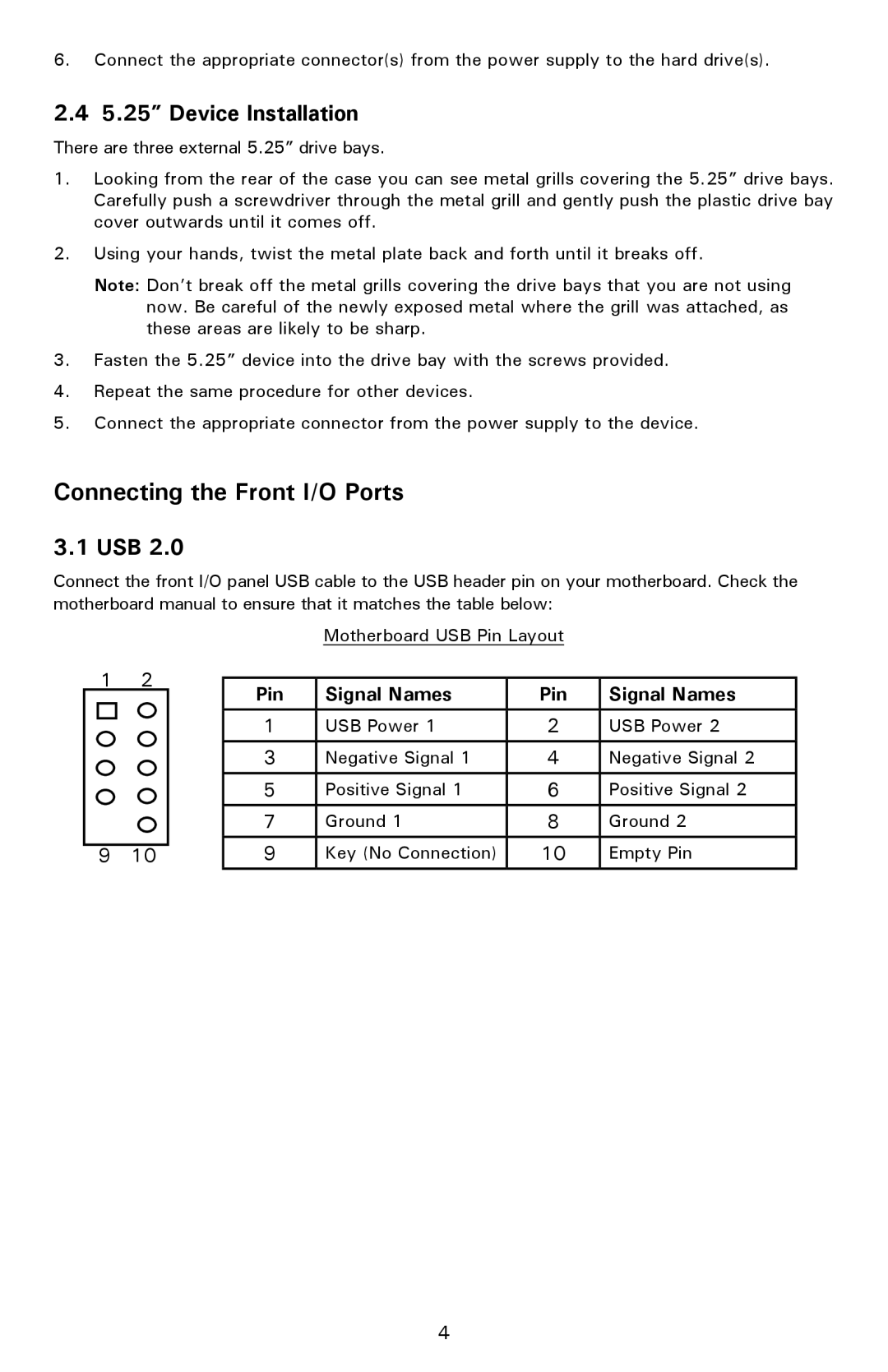
Connect the front I/O panel USB cable to the USB header pin on your motherboard. Check the motherboard manual to ensure that it matches the table below:
12
9 10
Motherboard USB Pin Layout
Pin | Signal Names | Pin | Signal Names |
1 | USB Power 1 | 2 | USB Power 2 |
3 | Negative Signal 1 | 4 | Negative Signal 2 |
|
|
|
|
5 | Positive Signal 1 | 6 | Positive Signal 2 |
|
|
|
|
7 | Ground 1 | 8 | Ground 2 |
|
|
|
|
9 | Key (No Connection) | 10 | Empty Pin |
|
|
|
|
4