Installation
Physical Description
Rear
Toolless mounting pegs allow for installation in APC NetShelter® VX and SX racks and enclosures without using any
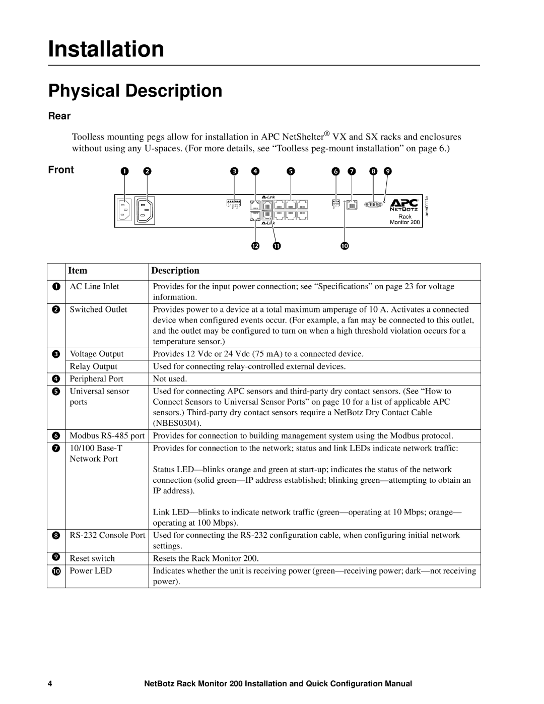
Front
| Item | Description |
|
|
|
| AC Line Inlet | Provides for the input power connection; see “Specifications” on page 23 for voltage |
|
| information. |
| Switched Outlet | Provides power to a device at a total maximum amperage of 10 A. Activates a connected |
|
| device when configured events occur. (For example, a fan may be connected to this outlet, |
|
| and the outlet may be configured to turn on when a high threshold violation occurs for a |
|
| temperature sensor.) |
| Voltage Output | Provides 12 Vdc or 24 Vdc (75 mA) to a connected device. |
| Relay Output | Used for connecting |
| Peripheral Port | Not used. |
| Universal sensor | Used for connecting APC sensors and |
| ports | Connect Sensors to Universal Sensor Ports” on page 10 for a list of applicable APC |
|
| sensors.) |
|
| (NBES0304). |
| Modbus | Provides for connection to building management system using the Modbus protocol. |
| 10/100 | Provides for connection to the network; status and link LEDs indicate network traffic: |
| Network Port | Status |
|
| |
|
| connection (solid |
|
| IP address). |
|
| Link |
|
| operating at 100 Mbps). |
| Used for connecting the | |
|
| settings. |
| Reset switch | Resets the Rack Monitor 200. |
| Power LED | Indicates whether the unit is receiving power |
|
| power). |
4 | NetBotz Rack Monitor 200 Installation and Quick Configuration Manual |