PUSH TO OPEN INSTALLATION
STEP 1 PIVOT ARM (s) INSTALLATION
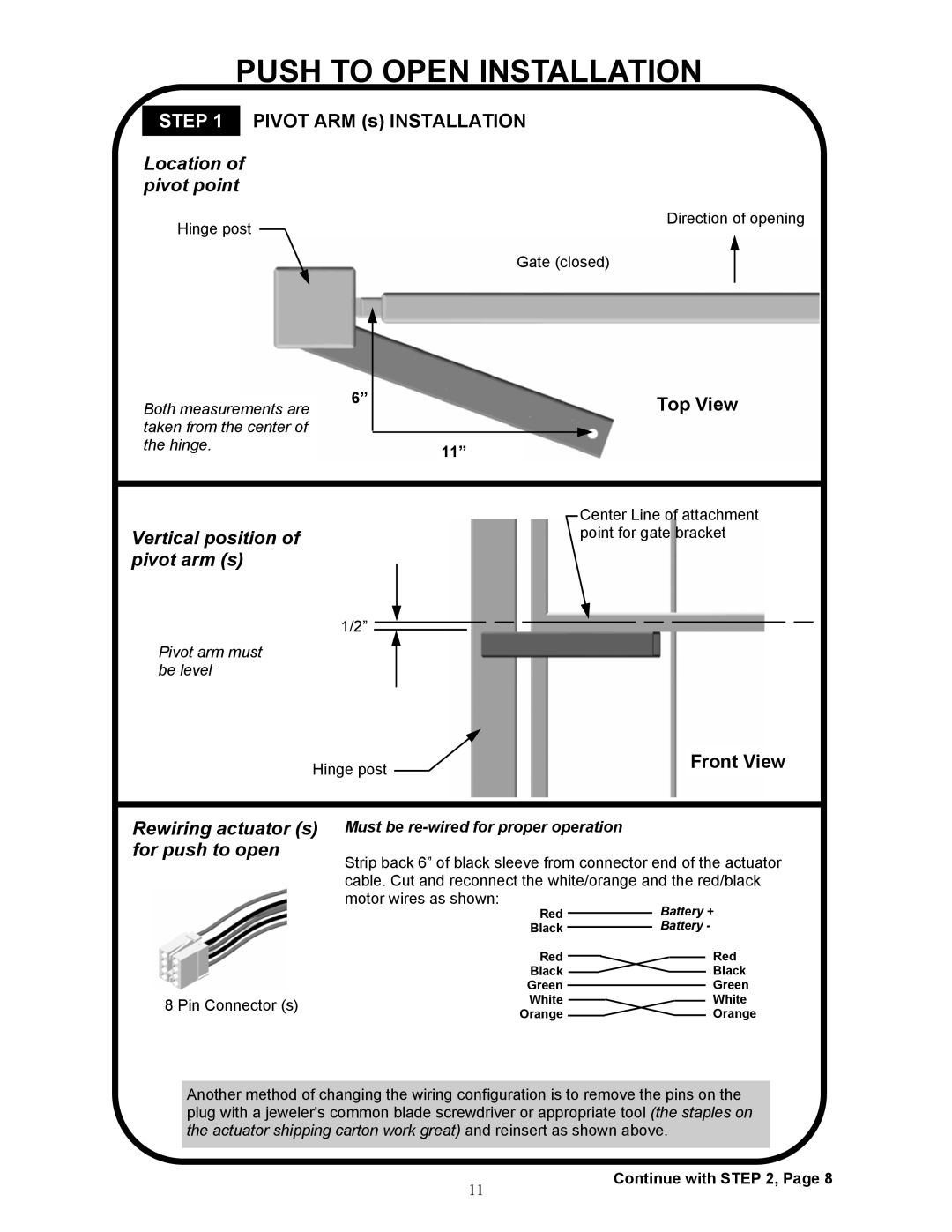
Location of pivot point
Hinge post |
| Direction of opening |
| Gate (closed) | |
|
|
|
| 6” |
|
|
| Top View |
| Both measurements are | |||||
| taken from the center of |
|
|
|
|
|
| the hinge. |
| 11” |
|
|
|
|
|
|
|
|
| |
|
|
|
|
|
|
|
|
|
|
|
|
|
|
|
|
|
|
|
|
|
|
|
|
|
|
| Center Line of attachment |
|
|
|
|
|
| |
Vertical position of |
|
|
|
| point for gate bracket | |
pivot arm (s) |
|
|
|
|
| |
1/2”
Pivot arm must be level
Hinge post |
|
| Front View |
| |||
|
|
|
|
Rewiring actuator (s) for push to open
8 Pin Connector (s)
Must be re-wired for proper operation
Strip back 6” of black sleeve from connector end of the actuator cable. Cut and reconnect the white/orange and the red/black motor wires as shown:
Red | Battery + |
Black | Battery - |
Red | Red |
Black | Black |
Green | Green |
White | White |
Orange | Orange |
Another method of changing the wiring configuration is to remove the pins on the plug with a jeweler's common blade screwdriver or appropriate tool (the staples on the actuator shipping carton work great) and reinsert as shown above.
11
Continue with STEP 2, Page 8