Manuals
/
Apollo
/
Baby
/
Safety Gate
Apollo
1650ETL, 1550ETL
installation manual
GateLink Connector
Models:
1650ETL
1550ETL
1
14
23
23
Download
23 pages
39.89 Kb
11
12
13
14
15
16
17
18
Install
Connecting the Actuator s
Warranty
GateLink Connector
Safety
Page 14
Image 14
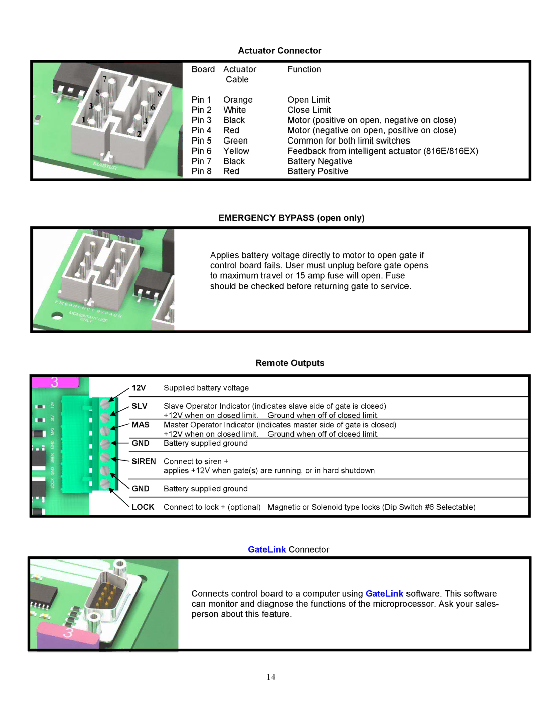
Actuator Connector
EMERGENCY BYPASS (open only)
Remote Outputs
GateLink
Connector
14
Page 13
Page 15
Page 14
Image 14
Page 13
Page 15
Contents
Installation Manual
Contents
Important Safety Instructions
Applications
PRE-INSTALLATION Checklist
Consider safety and access options. Recommend if needed
Parts Identification
Options
Pivot arm
Location of Pivot Point
Vertical position
Connecting the Actuator s
Gate Bracket Installation
1550ETL / 1650ETL Actuator Option
Top View
Push to Open Installation
Rewiring actuator s for push to open
Pivot arm s
Programming Instructions
835/836 Control Board Parts Identification
GateLink Connector
Adjustments Push Buttons Jumpers
OFF
Optional Device Inputs
Apollo Gate Operators, Inc
Apollo Gate Operators Receiver Options
Symptom Gate surges too much. Does not run smooth
Symptom Gate opens OK but after closing, opens back up
Symptom Gate moves only a few feet, then stops or reverses
Symptom Transmitter works, but not very far
Symptom Gate randomly opens, closes, or stops for no reason
Symptom Gate will not open or close
Dual Boards
Limited TWO-YEAR Warranty
Top
Page
Image
Contents