VENTILATION (continued)
DETERMINE VENTILATION REQUIREMENTS
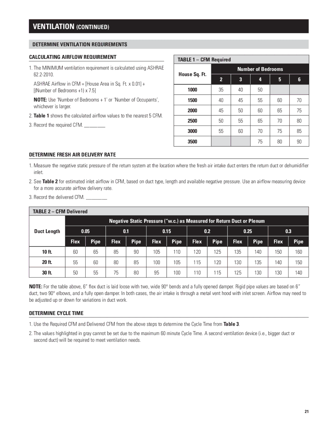
CALCULATING AIRFLOW REQUIREMENT
1.The MINIMUM ventilation requirement is calculated using ASHRAE
ASHRAE Airflow in CFM = [House Area in Sq.. Ft.. x 0..01] + [(Number of Bedrooms +1) x 7..5]
NOTE: Use ‘Number of Bedrooms + 1’ or ‘Number of Occupants’, whichever is larger..
2.Table 1 shows the calculated airflow values to the nearest 5 CFM..
3.Record the required CFM.. ________
DETERMINE FRESH AIR DELIVERY RATE
Table 1 – CFM Required
House Sq. Ft. |
| Number of Bedrooms |
| |||
2 | 3 | 4 | 5 | 6 | ||
| ||||||
|
|
|
|
|
| |
1000 | 35 | 40 | 50 |
|
| |
|
|
|
|
|
| |
1500 | 40 | 45 | 55 | 60 | 70 | |
|
|
|
|
|
| |
2000 | 45 | 50 | 60 | 65 | 75 | |
|
|
|
|
|
| |
2500 | 50 | 55 | 65 | 70 | 80 | |
|
|
|
|
|
| |
3000 | 55 | 60 | 70 | 75 | 85 | |
|
|
|
|
|
| |
3500 |
|
| 75 | 80 | 90 | |
|
|
|
|
|
| |
1.Measure the negative static pressure of the return system at the location where the fresh air intake duct enters the return duct or dehumidifier inlet..
2See Table 2 for estimated inlet airflow in CFM, based on duct type, length and available negative pressure.. Use an airflow measuring device for a more accurate airflow delivery rate..
3. Record the delivered CFM.. ________
Table 2 – CFM Delivered
|
|
|
| Negative Static Pressure (“w.c.) as Measured for Return Duct or Plenum |
|
|
| |||||||||||
Duct Length |
| 0.05 | 0.1 |
| 0.15 |
|
| 0.2 |
| 0.25 |
| 0.3 | ||||||
| Flex |
| Pipe | Flex | Pipe | Flex | Pipe | Flex |
| Pipe | Flex |
| Pipe | Flex |
| Pipe | ||
|
|
|
|
|
|
|
|
|
|
|
|
|
|
|
|
|
| |
10 ft. | 60 |
| 65 | 85 |
| 90 | 105 |
| 110 | 120 |
| 125 | 135 |
| 140 | 150 |
| 160 |
|
|
|
|
|
|
|
|
|
|
|
|
|
|
|
|
|
|
|
20 ft. | 55 |
| 60 | 80 |
| 85 | 100 |
| 105 | 115 |
| 120 | 130 |
| 135 | 140 |
| 150 |
|
|
|
|
|
|
|
|
|
|
|
|
|
|
|
|
|
|
|
30 ft. | 50 |
| 55 | 75 |
| 80 | 95 |
| 100 | 110 |
| 115 | 125 |
| 130 | 130 |
| 140 |
|
|
|
|
|
|
|
|
|
|
|
|
|
|
|
|
|
|
|
NOTE: For the table above, 6” flex duct is laid loose with two, wide 90° bends and a fully opened damper. Rigid pipe values are based on 6” duct, two 90° elbows, and a fully open damper.. In both cases, the air intake is through a metal vent hood with inlet screen.. Airflow may need to be adjusted up or down for variations in duct work..
DETERMINE CYCLE TIME
1.Use the Required CFM and Delivered CFM from the above steps to determine the Cycle Time from Table 3..
2.The values highlighted in gray cannot be set due to the maximum 60 minute Cycle Time.. A second ventilation device (i..e.., bigger duct or second duct) will be required to meet ventilation needs..
21