Table 1.4: Internal Connector
JLVDS1 | LVDS connector | HIROSE | 27 |
|
| 1.25 V |
|
JBKL1 | LCD Inverter connector | 5 x 1 header, | 28 |
|
| pitch 2.00 mm |
|
JDIO1 | Digital I/O connector | 5 x 2 header, | 28 |
|
| pitch 2.00 mm |
|
JSPI1 | SPI connector | 4 x 2 header, | 29 |
|
| pitch 2.5 4mm |
|
SPDIF_OUT2 | Digital Audio connector | 4 x 1 header, | 29 |
|
| pitch 2.54 mm |
|
SATA1,2,3 | Serial ATA connectors 1,2,3 | 30 | |
| [black] |
|
|
USB3 | USB 2.0 connector | 5 x 2 header, | 30 |
|
| pitch 2.54 mm |
|
USB4 | USB 2.0 connector | 5 x 2 header, | 30 |
|
| pitch 2.54 mm |
|
USB5 | USB 2.0 connector | 5 x 2 header, | 30 |
|
| pitch 2.54 mm |
|
1.4Central Processing Unit (CPU)
The motherboard comes with a surface mount
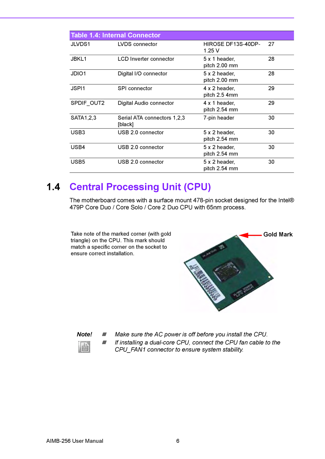
Take note of the marked corner (with gold |
|
| Gold Mark |
| |||
|
| ||
triangle) on the CPU. This mark should |
|
|
|
match a specific corner on the socket to |
|
|
|
ensure correct installation. |
|
|
|
Note! ! Make sure the AC power is off before you install the CPU.
!If installing a
6 |
